Components
MAX485 Alternatives: Robust and Isolated RS-485 Transceivers, Chosen Before the EMC Lab
A MAX485 alternative can mean a more robust non-isolated transceiver or a galvanically isolated one, and the MAX485 itself has no isolation barrier. This guide compares the TI THVD1450, ADI ADM2582E/87E and TI ISO1410/50 on isolation, CMTI, ESD and surge, from each part's datasheet.
Last updated: October 2026. Isolation, CMTI, ESD, and surge figures below are quoted from the named parts' datasheets, at the revisions named in the text; verify against the exact part and revision, and confirm current safety-agency certifications, before you design one in.
The short version
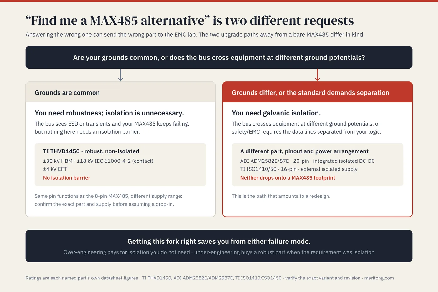
"Find me a MAX485 alternative" can mean two different requests, and answering the wrong one can send an RS-485 link into the electromagnetic compatibility (EMC) lab with the wrong part. The first asks for a more robust non-isolated transceiver, for a bus whose grounds are common but which sees electrostatic discharge (ESD) or fast transients. The second asks for a part that keeps working across a ground-potential difference, or that meets a safety or EMC requirement for electrical separation, and the answer to that request is galvanic isolation, from an isolated RS-485 transceiver or from discrete isolation around a transceiver (see the FAQ).
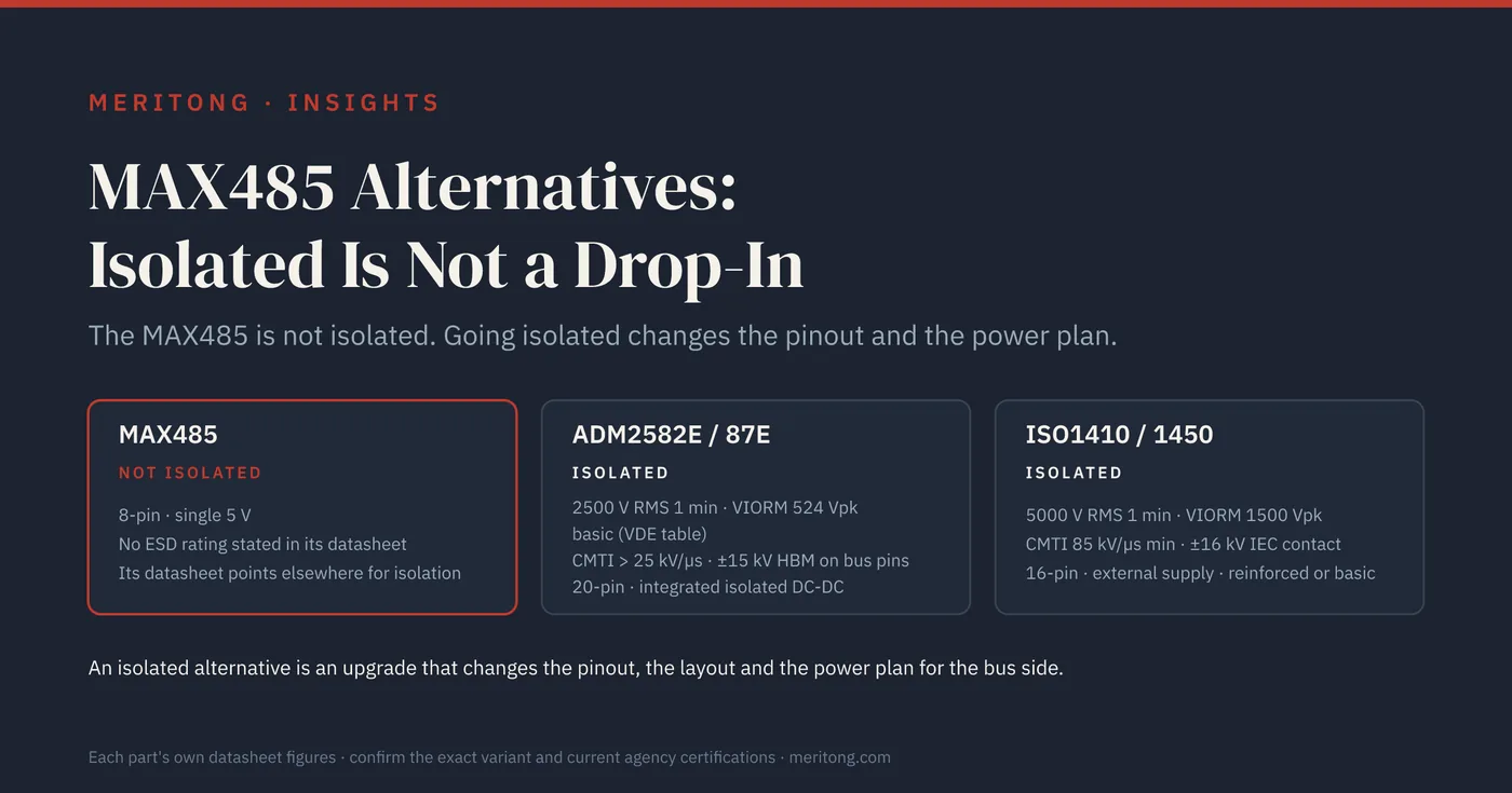
Everything else depends on one fact: the MAX485 is not isolated. Its datasheet (19-0122 Rev 10, September 2014) describes no isolation barrier and, for isolated RS-485 applications, refers the reader to the MAX253 and MAX1480 data sheets. An isolated part therefore cannot be placed on a MAX485 footprint: it needs a separate ground and isolated power on the bus side of its barrier, whereas the MAX485 has one ground pin shared by logic and bus. At device level, four specifications bear on the choice: isolation, common-mode transient immunity (CMTI), ESD and surge. The two requests separate on whether the grounds at either end of the bus are common or different, and on whether a safety or EMC requirement demands electrical separation.
| Issue | What can go wrong | When it matters | Who decides | How to verify |
|---|---|---|---|---|
| No isolation on the MAX485 | The bus has no barrier against a ground-potential difference | Grounds differ, or a safety or EMC requirement demands separation | Hardware design with the safety lead | Establish the grounding of both ends before choosing a part |
| ESD and fast transients on a common-ground bus | Bus pins fail ESD or electrical fast transient (EFT) testing | The product's environment exposes the bus to ESD or fast transients | Hardware design with the EMC lead | Compare the datasheet International Electrotechnical Commission (IEC) 61000-4-2 and -4-4 ratings, then test the interface |
| Isolation grade | Basic isolation where the safety case needs reinforced | The barrier is part of the protection against electric shock | Safety lead | Decide the grade against the product's safety standard, then pick the part-number suffix |
| Footprint and supply | An isolated part does not fit the MAX485 footprint | Any move from MAX485 to an isolated part | Layout | New layout with creepage and clearance under the barrier, plus a bus-side power plan |
| Certification status | A certificate the safety case relies on is still pending | The design cites VDE 0884-17 certification | Compliance | Check the current certificate itself, because the datasheet's status line records only the state at that revision |
First, which problem are you solving?
Two upgrade paths lead away from a bare MAX485, and they differ in kind:
You need more robustness, and isolation is unnecessary: your grounds are common, but the bus sees ESD or transients and your MAX485 keeps failing. What the link needs is a robust, non-isolated transceiver. The THVD1450 from Texas Instruments (TI), for example, is rated to ±30 kV human body model (HBM) and ±18 kV IEC 61000-4-2 (contact) ESD plus ±4 kV EFT on its bus pins, with no isolation barrier (THVD14xx datasheet SLLSEY3E, May 2019). Its 8-pin versions assign each pin the same function as the 8-pin MAX485, although its supply range differs (see the FAQ). That gives the bus pins stated ESD and EFT ratings where the MAX485 datasheet states none, without the isolated supply and the new layout that isolation requires.
You need galvanic isolation: your bus crosses between equipment at different ground potentials, or safety or EMC requirements demand that the data lines be electrically separated from your logic. Now you need galvanic isolation, which in this article means an isolated transceiver: a different part, a different pinout and a different power arrangement (the discrete alternative is covered in the FAQ).
Getting this fork right saves you from two opposite errors: over-engineering, which pays for isolation the product does not need, and under-engineering, which buys a robust part when the requirement was isolation. The rest of this article follows the isolation path, because that path is the one that amounts to a redesign.
What "survives the EMC sweep" means
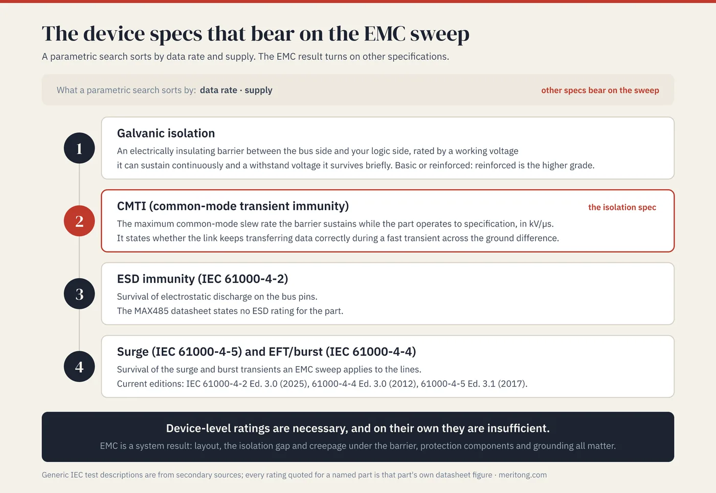
A parametric search sorts by data rate and supply. The device specifications that bear on whether an RS-485 interface passes EMC and electromagnetic interference (EMI) testing are different ones, and they are these:
Galvanic isolation: an electrically insulating barrier between the bus side and your logic side, rated by a working voltage it can sustain continuously and a withstand voltage it survives briefly. Check whether the isolation is basic or reinforced, since reinforced is the higher grade.
CMTI: the maximum common-mode voltage slew rate, in kV/µs, that the isolation barrier can sustain while the part keeps operating to specification. It states whether the link keeps transferring data correctly when a fast transient appears across the ground difference.
ESD immunity (IEC 61000-4-2): survival of electrostatic discharge on the bus pins.
Surge (IEC 61000-4-5) and EFT/burst (IEC 61000-4-4): survival of the surge and burst transients an EMC sweep applies to the lines. The datasheets quoted here give no IEC 61000-4-5 surge rating for the bus pins; the surge figures they state concern the isolation barrier.
Strong ratings on these make a pass possible without guaranteeing it, because EMC is a result of the whole interface (see the FAQ). A bare MAX485 gives you no device-level ESD figure to start from: its datasheet states no ESD rating for the part at all. The IEC standards define equipment-level tests; the current editions are IEC 61000-4-2 Edition 3.0 (2025), IEC 61000-4-4 Edition 3.0 (2012) and IEC 61000-4-5 Edition 3.1 (2017). The numbers below are each vendor's own device ratings, so if your test plan names an edition, ask the vendor which edition a rating was tested against.
The isolated alternatives
Two isolated RS-485 families follow, described from their current datasheets. The figures are family-level: the exact orderable part number decides the isolation grade and the data rate, so confirm both against it.
Analog Devices (ADI) ADM2582E / ADM2587E: an isolated RS-485 transceiver with an integrated isolated DC-DC converter (isoPower), so that the bus side is powered across the barrier without a separate isolated supply. Isolation is rated at 2500 V RMS for 1 minute (UL 1577) and a maximum repetitive isolation voltage (VIORM) of 524 V peak, with CMTI greater than 25 kV/µs and ±15 kV HBM ESD on the bus pins, in a 20-pin package (ADM2582E/ADM2587E datasheet Rev. H, February 2025). The datasheet describes the isolation as suitable for basic electrical isolation only, and lists the DIN EN IEC 60747-17 (VDE 0884-17) certificate as pending. The same revision is inconsistent on the grade: its regulatory table lists the pending VDE entry as reinforced insulation at 560 V peak and the granted China Quality Certification Centre (CQC) GB4943.1 certificate as basic insulation at 820 V rms and reinforced insulation at 410 V rms, whereas its VDE 0884-17 insulation tables give 524 V peak as basic insulation, so confirm the grade with ADI before a safety case relies on it. ADI's product pages show both parts in production and list the ADM2567E and ADM2565E (for the ADM2582E) and the ADM2563E and ADM2561E (for the ADM2587E) as recommended for new designs; this article has not assessed those parts. The integrated DC-DC converter is the principal convenience, since one part supplies isolated data and isolated power. Its trade-off bears directly on EMC: the datasheet states that the converter's high-frequency currents "can propagate in circuit board ground and power planes, causing edge and dipole radiation", and it devotes a layout section to managing them.
Texas Instruments ISO1410 / ISO1430 / ISO1450: isolated RS-485 transceivers that require an externally supplied isolated bus rail, with no integrated DC-DC converter (ISO14xx datasheet SLLSF22I, revised August 2026). They specify a UL 1577 withstand of 5000 V RMS for 1 minute, a VIORM of 1500 Vpk and a maximum working isolation voltage (VIOWM) of 1060 Vrms, a CMTI of 85 kV/µs (minimum), 100 kV/µs typical, and ±30 kV HBM and ±16 kV IEC 61000-4-2 (contact) ESD on the bus, in a 16-pin package. TI sells each part in two isolation grades as separate stock-keeping units (SKUs): the ISO141x, ISO143x and ISO145x are the reinforced versions, and the same numbers with a B suffix are the basic versions. TI's page-1 comparison gives a surge test voltage of 10000 Vpk for the reinforced and 6000 Vpk for the basic grade, while its insulation-specifications table states the maximum surge isolation voltage only in rows labelled ISO141x and ISO141xB. The trade-off against the ADI part is that you supply the isolated rail yourself.
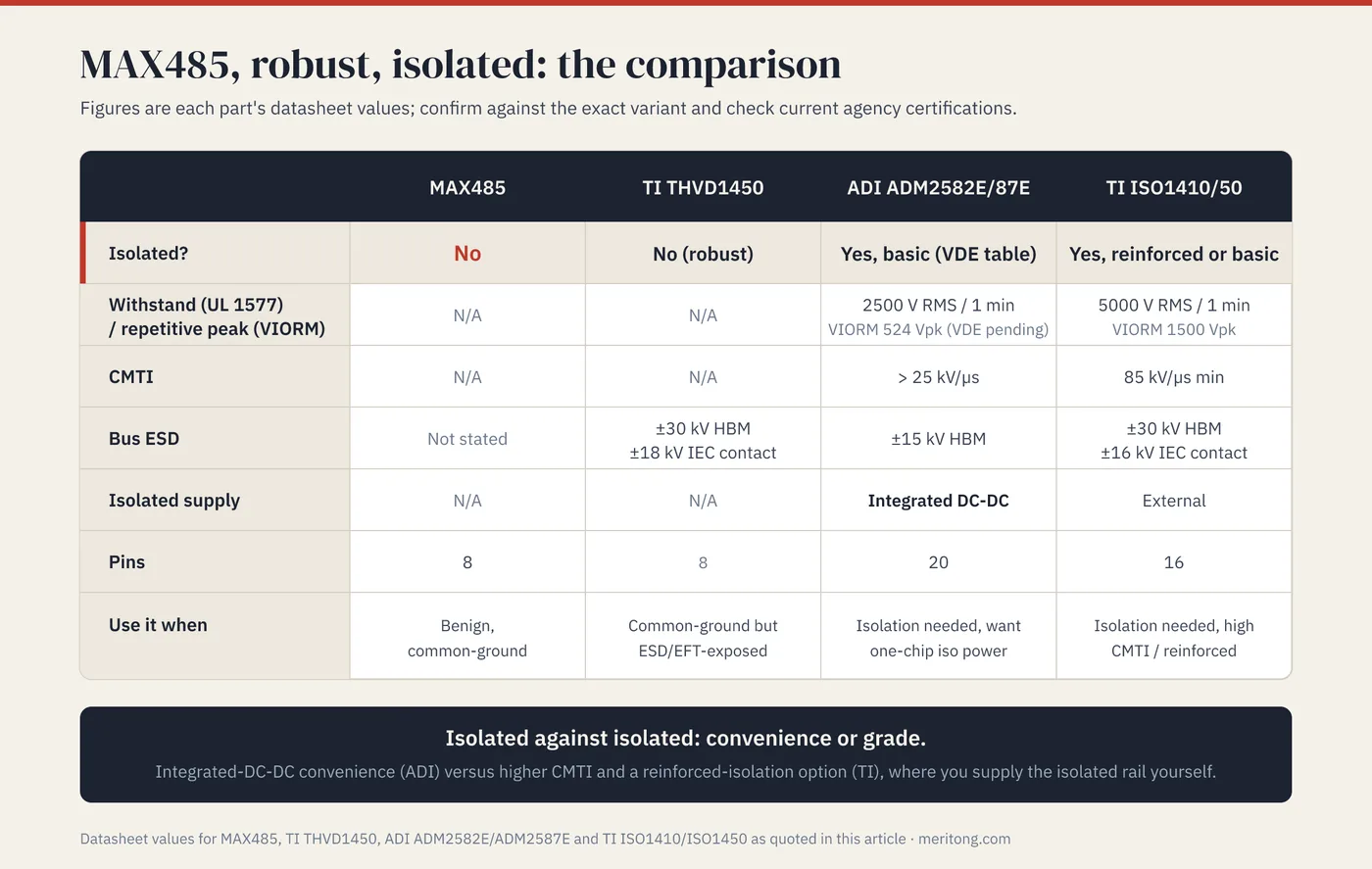
The principal trade-off between them is the convenience of an integrated DC-DC converter (ADI) against higher CMTI and a reinforced-isolation option (TI). Either one adds an isolation barrier; whether its grade meets the requirement is the safety lead's decision (see the FAQ on isolation voltage).
The comparison
| MAX485 | THVD1450 | ADM2582E/87E | ISO1410/50 | |
|---|---|---|---|---|
| Isolated? | No | No (robust) | Yes, basic per its VDE 0884-17 table (grade inconsistent; see text) | Yes, reinforced or basic (B suffix) |
| Withstand (UL 1577, 1 min) | N/A | N/A | 2500 V RMS | 5000 V RMS |
| Repetitive peak (VIORM) | N/A | N/A | 524 Vpk (VDE certificate pending) | 1500 Vpk |
| CMTI | N/A | N/A | > 25 kV/µs (at 1 kV) | 85 kV/µs min (at 1200 V) |
| Bus ESD | Not stated | ±30 kV HBM / ±18 kV IEC contact | ±15 kV HBM | ±30 kV HBM / ±16 kV IEC contact |
| Isolated supply | N/A | N/A | Integrated DC-DC | External |
| Pins | 8 | 8 | 20 | 16 |
| Use it when | Benign, common-ground | Common-ground but ESD/EFT-exposed | Isolation needed, want one-chip iso power | Isolation needed, need high CMTI / reinforced |
(Figures are each part's datasheet values: MAX481–MAX491/MAX1487 datasheet 19-0122 Rev 10, September 2014, the PDF ADI serves, although its product page labels the link Rev. 11; THVD14xx SLLSEY3E, May 2019; ADM2582E/ADM2587E Rev. H, February 2025; ISO14xx SLLSF22I, August 2026. Confirm against the exact variant and check current agency certifications.)
The swap reality: this is an interface redesign
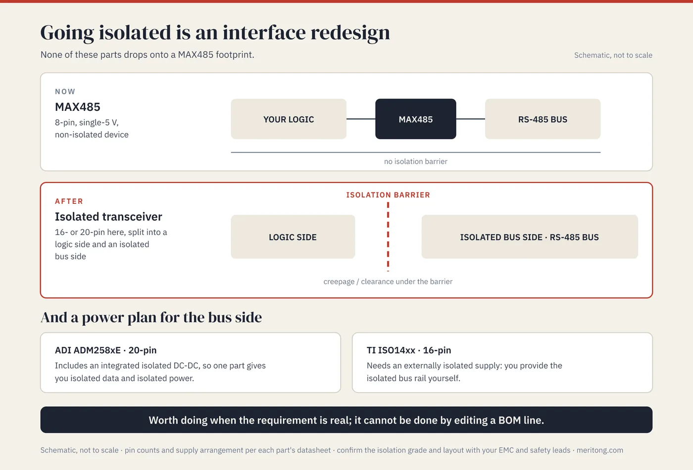
The MAX485 is an 8-pin, single-5 V, non-isolated device. Because the isolated parts in this article are 16- or 20-pin, because they split into a logic side and an isolated bus side, and because they either need an externally isolated supply (TI ISO14xx) or include an integrated isolated DC-DC converter (ADI ADM258xE), none of them drops onto a MAX485 footprint. Moving to isolation therefore means redesigning that interface: a new part, a new layout with a real isolation gap and creepage and clearance under the barrier, and a power plan for the bus side. It is worth doing when the requirement is real, and it cannot be done by editing a bill of materials (BOM) line. (This is general engineering guidance: your EMC and safety leads should confirm the isolation grade and layout for your product.)
Verifying a candidate before you commit
- Establish the grounding at both ends of the bus and whether a safety or EMC requirement demands separation; that decision chooses between the robust and the isolated path.
- Obtain the current datasheet revision for the exact orderable part number, and read the isolation grade, the CMTI with its test conditions, and the bus-pin ESD and EFT ratings with their test methods.
- For an isolated part, check the current VDE 0884-17 and UL 1577 certificates themselves, because the datasheet's status line records only the state at that revision, and decide basic or reinforced with your safety lead against the product's safety standard.
- Lay out the barrier with the creepage and clearance your equipment standard requires, plan the bus-side supply, and for an integrated DC-DC part follow the datasheet's emissions layout guidance.
- Test the assembled interface at the IEC 61000-4-2, -4-4 and -4-5 levels and editions your product standard and test plan name.
These steps identify the principal risks; final qualification still tests the exact part in the finished interface.
FAQ
Is there a drop-in isolated replacement for the MAX485?
No. An isolated transceiver needs a separate ground and isolated power on the bus side of its barrier, which the MAX485's 8-pin pinout, with one ground pin shared by logic and bus, cannot provide. The isolated RS-485 parts in this article are 16- or 20-pin, each with a separate isolated bus side and a power arrangement to match. Going isolated therefore requires a new layout and either an isolated supply or a part with an integrated isolated DC-DC converter.
My MAX485 keeps failing on ESD but my grounds are common; do I need isolation?
Probably not; you may need only a robust non-isolated transceiver. Parts such as TI's THVD1450 add large ESD and EFT protection (for example ±30 kV HBM, ±18 kV IEC contact, ±4 kV EFT) with no isolation barrier, which avoids the isolated supply and the barrier layout that going isolated requires. Reserve isolation for the cases where the grounds differ or the standard demands it.
What is CMTI and why does it matter for RS-485?
Common-mode transient immunity (CMTI) is the maximum common-mode voltage slew rate, in kV/µs, that the isolation barrier can sustain while the part keeps operating to specification. On an isolated bus between different ground potentials, a large transient appears as exactly such a common-mode step, which is why a high CMTI rating matters: the TI ISO14xx specifies 85 kV/µs minimum, measured with a 1200 V common-mode step, and the ADM2582E/87E specifies 25 kV/µs with a 1 kV common-mode voltage and an 800 V transient magnitude. Compare the test conditions as well as the figures.
ADM2582E or ISO1410: which isolated part?
The ADM2582E/87E integrates the isolated DC-DC converter, so it offers a one-chip route to isolated data and power, with basic isolation under its VDE 0884-17 table, although its regulatory table also lists reinforced ratings, so confirm the grade with ADI; its integrated converter also brings the radiated-emissions layout work that its datasheet describes. The ISO1410/50 requires you to supply the isolated rail, yet it offers higher CMTI and a reinforced-isolation option. Choose according to whether you value integrated isolated power (ADI) or a reinforced option and higher CMTI (TI).
Will any of these help me pass the EMC sweep on their own?
They give you the device-level ratings that make a pass possible, but EMC is a system result: layout, the isolation gap and creepage under the barrier, protection components, and grounding all matter. The transceiver specifications relevant to your path are necessary, and on their own they are insufficient, because the result depends on the interface designed around the part.
Is the THVD1450 a drop-in for a MAX485?
In its 8-pin SOIC, VSSOP and VSON packages, the THVD1450 assigns each pin the same function as the 8-pin MAX485 (pin 1 receiver output through pin 8 supply); the SOIC version corresponds to the MAX485's 8-pin SO package and the VSSOP version is a candidate against its 8-pin µMAX package, so confirm the land pattern against both package drawings. TI describes the SOIC version as offered "for Drop-in Compatibility", without naming the part it replaces. Its supply is specified from 3 V to 5.5 V against the MAX485's 4.75 V to 5.25 V, and its absolute maximum supply is 7 V against the MAX485's 12 V, so check your supply rail and its transients. A drop-in verdict needs the exact orderable part numbers on both sides and a test in your circuit. It is a suitable candidate when your grounds are common and the problem is ESD or transients. Where the problem is isolation, it is not the answer, because it has no isolation barrier.
How much isolation voltage do I need?
The answer is a safety-and-standards question for your product, and no single number settles it: which grade is required depends on the safety standard that applies to your product and on whether the barrier forms part of the protection against electric shock. The TI ISO14xx family offers reinforced and basic variants, so that you can buy the grade your safety case demands: decide the grade with your safety lead, then pick the SKU.
Can I add isolation around a MAX485 with external parts instead of changing the chip?
You can build discrete isolation, with digital isolators and an isolated supply around a transceiver, but it usually means more board area, more parts and more ways to get the barrier layout wrong than an integrated isolated transceiver such as the ADM2582E. The discrete route remains an option where no integrated part fits the data rate, supply or isolation grade you need.
Close
Whether a MAX485 alternative holds up in the EMC sweep depends on its isolation, CMTI, ESD and surge ratings and on the interface built around it, because a parametric match on data rate and supply says nothing about any of them.
If you are deciding whether your MAX485 needs a robust part or an isolated redesign, I can help you work through it, looking at the transceiver and the board around it, the firmware that drives its enable pins, and the sourcing of the parts together, particularly where that sourcing runs through China.
This article quotes the named parts' datasheets for isolation, CMTI, ESD, and surge ratings; generic IEC test definitions are from secondary sources, and one part's safety-agency certification was pending in the revision reviewed. It is general engineering guidance: verify the exact part, revision, and current certifications, and confirm your interface's EMC and isolation design with qualified engineers.
Typical dependencies by email
Examples from real hardware audits, sent occasionally.
Working through this right now? Free intro call → or write to me →
Is this question on your desk right now?
In the free potential check you tell me the type of components you use. After 30 minutes you know whether an audit is worth it.
Free intro call