Components
MP1584 / MP2307 Alternatives: Second-Sourcing the Buck on Every Cheap Module (and Why "3 A Step-Down" Isn't Drop-In)
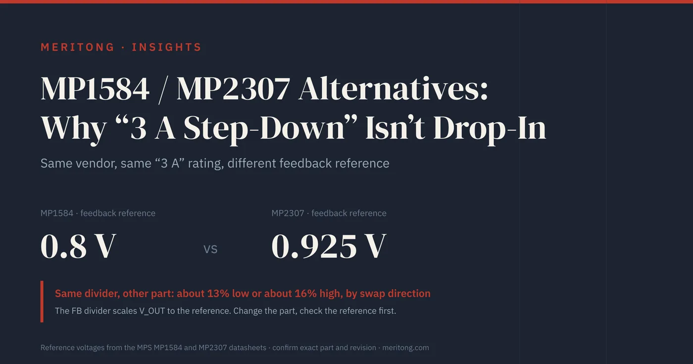
The MP1584 and the MP2307, two 3 A step-down converters from the same manufacturer, regulate their feedback pins to 0.8 V and 0.925 V, so the same resistor divider gives a different output voltage on each. Whether a buck-converter swap works turns on the feedback reference, the switching frequency, the control scheme and the input range.
Last updated: October 2026. Reference voltages, switching frequencies, input ranges and current ratings below are quoted from the named parts' datasheets at the revisions listed under the comparison table. The comparison is family-level: an orderable suffix can change the applicable datasheet, so verify against the exact part number and revision before you design one in.
The short version
The MP1584 and the MP2307, two 3 A step-down converters from the same manufacturer, regulate their feedback pins to different references: 0.8 V on the MP1584 and 0.925 V on the MP2307. A buck's output is set by a resistor divider that scales the output down to that reference, so the same divider on a different reference gives a different output voltage. A design tuned for an MP2307 that receives an "equivalent" part with a 0.8 V reference regulates about 13% low; a design tuned for an MP1584 that receives a part with a 0.925 V reference regulates about 16% high, an overvoltage the load may not tolerate. Whether a buck-converter swap works therefore turns on numbers that the phrase "pin-compatible 3 A step-down" does not state: the feedback reference, the switching frequency, the control scheme and the input range.
Monolithic Power Systems (MPS) now marks the MP1584 and the MP2307 as not recommended for new designs; both continue in production for existing customers, and MPS names the MP2338 and the MP2393 respectively as the alternatives for new designs (MP1584 product page, MP2307 product page, checked 13 October 2026). A manufacturer's own successor is still a different part with its own datasheet, and the checks below apply to it as to any other candidate.
The two parts are widely used, not least on the low-cost step-down modules sold under their names for board bring-up. When a product goes to production it needs a qualified second source, because a module is not a sourcing strategy and because counterfeit and over-rated modules have been documented (see the module section below). A candidate chosen by searching for "3 A buck converter" and taking the first match can regulate to the wrong voltage on the production board.
| Difference between parts | What can fail | When it matters | Who checks it | How to verify |
|---|---|---|---|---|
| Feedback reference | Output regulates to the wrong voltage | Whenever the divider is reused unchanged | Hardware design | Recompute the divider from the candidate's reference |
| Switching frequency | Excess ripple, inductor outside its ripple-current or saturation rating | Whenever the frequency differs from the original's | Hardware design | Re-select inductor and output capacitors from the candidate's datasheet |
| Control scheme | Instability or oscillation | Moving between current-mode and constant-on-time parts | Hardware design, layout | Follow the candidate's output-capacitor and layout guidance; measure load-step response |
| Input range and current limit | Part outside its rating at your supply or load | Supply above the candidate's input range, high step-down ratios, high ambient | Hardware design | Compare ranges; measure temperature rise at worst-case load |
Why a buck converter isn't a commodity swap
On the datasheet a step-down converter presents itself as a black box with roughly the same five pins on every part: input, output, feedback, enable and ground. It is not a commodity, because the numbers behind those pins differ in ways that change your board. Three of those numbers each reach into a different part of the design: the feedback reference into the resistor divider, the switching frequency into the inductor and the capacitors, and the control scheme into the output capacitor and the layout.
The feedback reference voltage sets your output. In an adjustable-output buck, the output voltage is programmed with two resistors from the output to the feedback (FB) pin, which divide V_OUT down until it equals the chip's internal reference. The MP1584 datasheet is explicit that its FB divider scales the output "equal to the internal +0.8V reference", whereas the MP2307 datasheet states that "the feedback threshold is 0.925V." The same divider network therefore gives different regulated outputs on the two parts. For a second-source decision this number sets the output voltage directly, yet it does not appear in the one-line product description, so a search on "3 A step-down" does not bring it to the surface.
The switching frequency sets your inductor and caps. The MP1584's frequency is programmable from 100 kHz to 1.5 MHz, whereas the MP2307 switches at a fixed 340 kHz. A converter's inductor and output-capacitor values are chosen for its switching frequency, which is why a 340 kHz design and a 1.5 MHz design want different inductors for the same output. Swap the controller without re-checking the passives, and you can end up outside the inductor's ripple-current or saturation envelope.
The control scheme sets your stability and layout. Not all of these parts regulate the same way internally. The MP1584 uses peak-current-mode control with an external compensation network on its COMP pin, the output of the internal error amplifier. Two of the alternatives below instead use a constant-on-time (COT) family of control: D-CAP2 from Texas Instruments (TI) and AHP-COT (adaptive hysteresis and pseudo-constant on-time control) from SGMicro. Silergy describes the SY8113B's control as an "instant PWM architecture" (PWM: pulse-width modulation) without classifying it further, and does not call it current-mode control. The stability of the COT parts depends on the output capacitor's capacitance and equivalent series resistance (ESR). TI's TPS563201 datasheet states that the part is "intended for use with ceramic or other low ESR capacitors" and recommends 20 µF to 68 µF, and TI's application report on D-CAP2 stability shows that a large output capacitance with a small ESR lowers the loop bandwidth, and that "if the phase margin is lower than 45°, the system can be unstable" (SLVAE93, December 2019). A COT part dropped onto a board laid out for a current-mode part, or paired with an output capacitor outside its datasheet's conditions, can therefore oscillate. These control philosophies are not interchangeable.
The numbers that matter, side by side
The figures below come from the parts' own datasheets, and the two MPS parts you are most likely trying to replace already disagree on the reference voltage:
| Part | Vendor | FB reference | Switching freq | Input range | Rated current | Control |
|---|---|---|---|---|---|---|
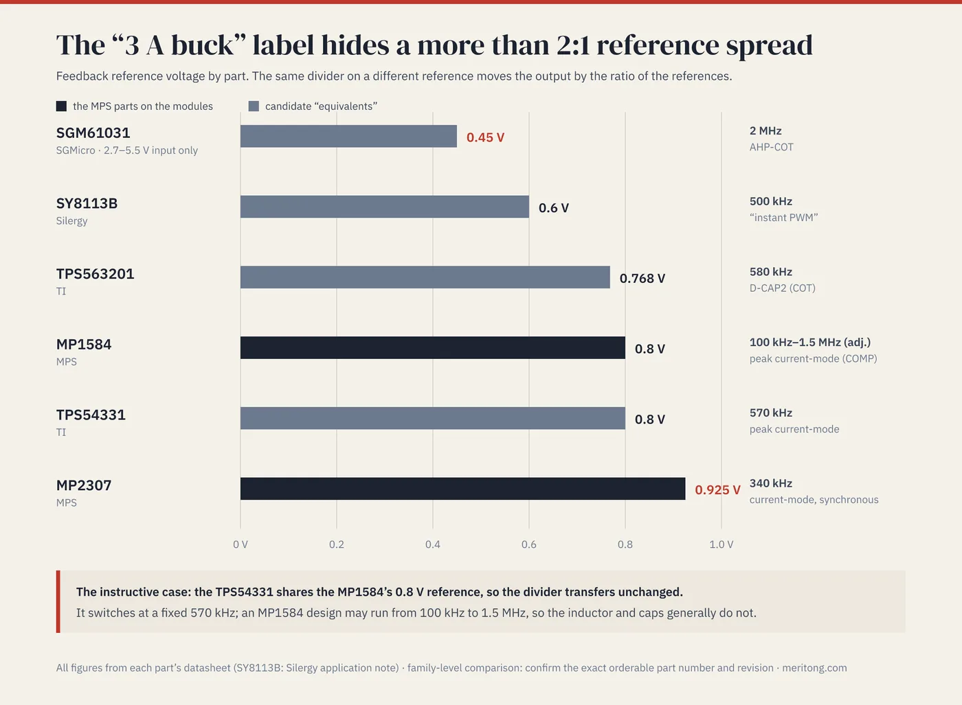
| MP1584 | MPS | 0.8 V | 100 kHz–1.5 MHz (adj.) | 4.5–28 V | 3 A | peak current-mode (COMP) |
| MP2307 | MPS | 0.925 V | 340 kHz | 4.75–23 V | 3 A | current-mode, synchronous |
| TPS54331 | TI | 0.8 V | 570 kHz | 3.5–28 V | 3 A | peak current-mode |
| TPS563201 | TI | 0.768 V | 580 kHz | 4.5–17 V | 3 A | D-CAP2 (COT) |
| SY8113B | Silergy | 0.6 V | 500 kHz | 4.5–18 V | 3 A | "instant PWM" |
| SGM61031 | SGMicro | 0.45 V | 2 MHz | 2.7–5.5 V | 3 A | AHP-COT |
(Typical values for reference and frequency, specified ranges for input, read from each document's electrical-characteristics table or feature list. Sources: MPS MP1584 datasheet Rev. 1.0, 8 August 2011; MPS MP2307 datasheet Rev. 1.9, 28 May 2008; TI TPS54331, SLVS839H, revised October 2023; TI TPS563201, SLVSD90B, revised September 2024, continuous-mode reference; Silergy application note AN_SY8113B Rev. 0.1, undated, as hosted by LCSC; SGMicro SGM61031 Rev. A, October 2022. TPS54331 frequency at VIN = 12 V, 25 °C; SGM61031 reference at VIN = 3.6 V. Revisions checked 13 October 2026.)
Every one of these parts is a "3 A buck," yet the feedback reference ranges from 0.45 V to 0.925 V, a spread of more than 2:1. Any of them dropped onto a divider sized for a different reference moves the output by the ratio of the two references. The input column matters as well: the SGM61031 accepts only 2.7 V to 5.5 V, so it cannot replace either MPS part on an input above 5.5 V; it appears in the table as a data point for the reference spread. The TI TPS54331 shares the MP1584's 0.8 V reference exactly, so the divider does transfer unchanged; but it switches at a fixed 570 kHz, whereas an MP1584 design may run anywhere from 100 kHz to 1.5 MHz, so the inductor and output capacitors generally do not. There is no single part in that table for which the whole surrounding circuit can be copied unchanged.
How to second-source one of these
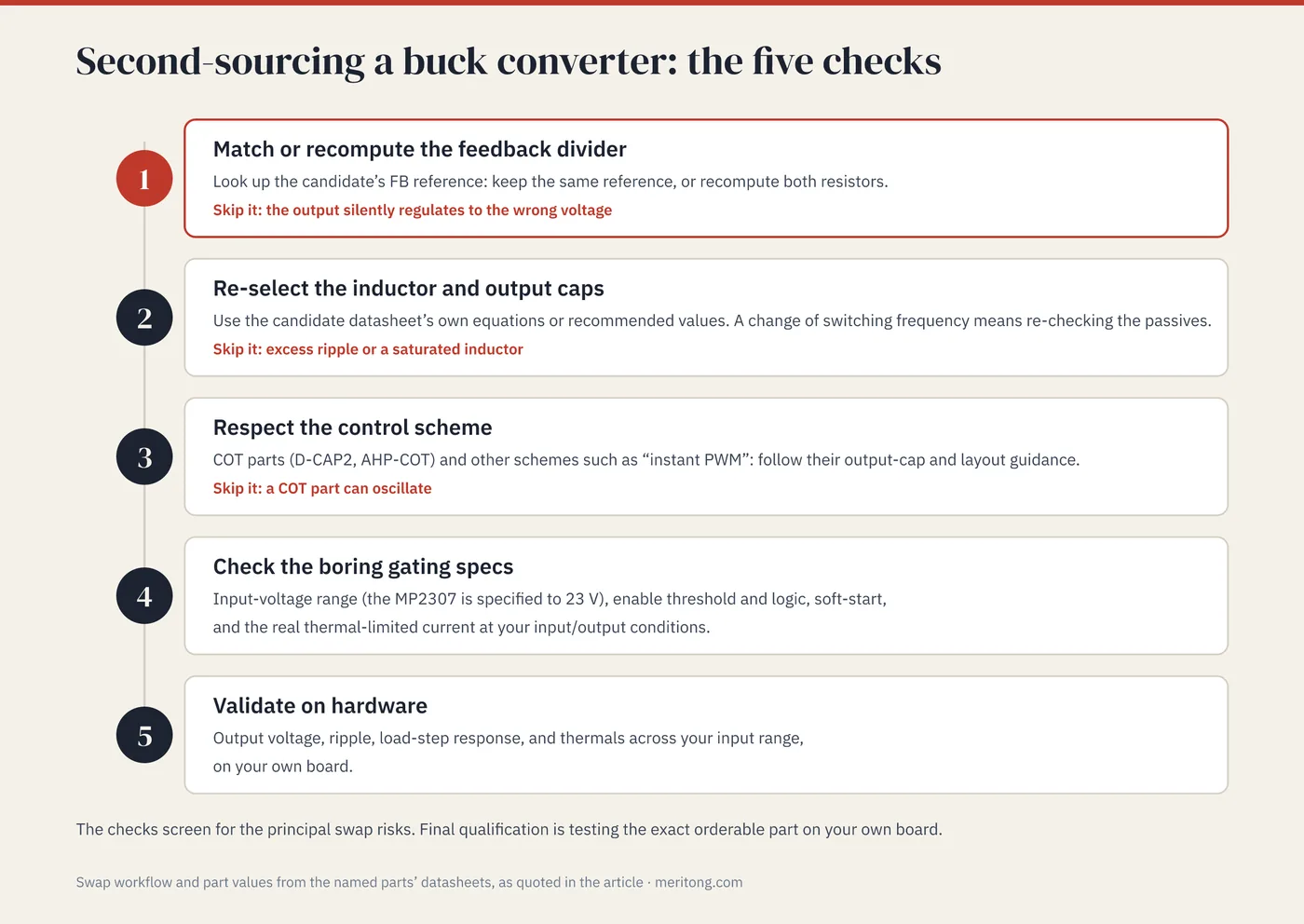
The swap is straightforward once it is treated as an engineering task, and it comes down to five checks:
Match or recompute the feedback divider to the new reference. Look up the candidate's FB reference voltage and either pick a part with the same reference, so that the divider transfers unchanged, or recompute the two resistors for the new reference. This is the step that, if skipped, silently sets your output wrong.
Re-select the inductor and output caps for the new switching frequency and control scheme. Use the candidate datasheet's own worked equations or its recommended values. A change of switching frequency means re-checking the passives, because values chosen for the old frequency can fall outside the new part's ripple-current, saturation or output-capacitor conditions.
Respect the control scheme. If you move to a COT part such as D-CAP2 or AHP-COT, or to another scheme such as "instant PWM", follow its output-capacitor requirements for capacitor type, capacitance and ESR and its layout guidance to the letter, because its stability depends on them. If you stay with current-mode control, keep the compensation approach and recompute any external compensation network from the new datasheet.
Check the boring gating specs: the input-voltage range (the MP2307 is specified to 23 V, and the candidates' maximum input voltages range from 5.5 V to 28 V), the enable-pin threshold and logic, soft-start, and the real thermal-limited current at your input and output conditions.
Then validate on hardware: output voltage, ripple, load-step response, and thermals across your input range, on your own board.
These five checks identify the principal risks of the swap; final qualification still tests the exact orderable part on your own board, in the intended operating conditions. Skip step 1, and the board regulates to the wrong voltage; skip step 2, and the penalty is excess ripple or a saturated inductor; skip step 3, and a COT part can oscillate.
A word on the modules themselves
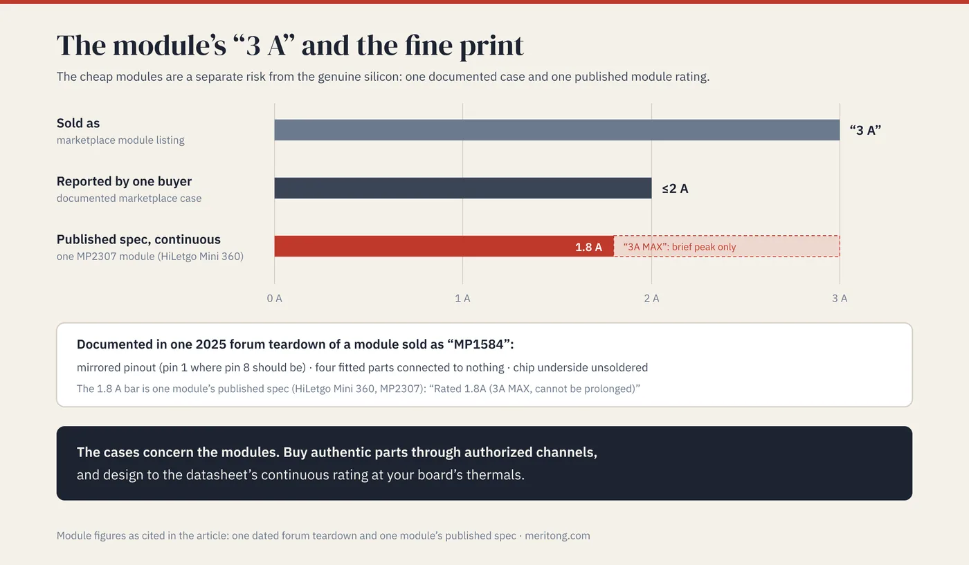
There is a second and separate reason for treating these parts with care: a module sold as an MP1584 with a counterfeit controller has been documented, and one MP2307 module's published specification rates it at 1.8 A continuous with 3 A only as a brief peak, which is part of why "the module works on my bench" is not evidence that the part will work in your product.
In October 2025 a member of the German electronics forum mikrocontroller.net documented a marketplace module sold as an MP1584EN. Its controller had a mirrored pinout, with pin 1 where pin 8 should be; four fitted components were connected to nothing; and the underside of the chip was left unsoldered. Posters in the thread identified the controller as a different part. A buyer review quoted in the same thread reported that a module's maximum load current "does not exceed 2A", on a listing that sold it as a 3 A module. The published specification for one MP2307-based module, HiLetgo's Mini 360, gives its output as "Rated 1.8A (3A MAX, cannot be prolonged)", which makes the "3 A" a brief peak and leaves 1.8 A as the continuous rating (as reproduced on manuals.plus; a retailer listing for the same module type carries the same rating). The genuine MPS parts are widely used and documented. What the two cases argue for is buying authentic parts through authorized channels and designing to the datasheet's continuous rating at your thermals. The distinction matters most at the moment you leave the module behind and put the bare integrated circuit on your own board.
FAQ
Can I drop a TPS54331 in for an MP1584 since they're both 0.8 V, 3 A?
The feedback divider transfers unchanged, since both parts use the same 0.8 V reference, and that removes the step that sets the output voltage. The TPS54331 nevertheless switches at a fixed 570 kHz, whereas an MP1584 design may run anywhere from 100 kHz to 1.5 MHz, so re-select the inductor and output capacitors for the new frequency using the TI datasheet's equations. Validate on your board.
Why does my "equivalent" buck output the wrong voltage?
One likely cause is a feedback-reference mismatch. Your divider was sized for the original part's reference, say 0.925 V, and the replacement uses a different one, say 0.8 V or 0.6 V, so the same resistors regulate to a different output. Measure the FB pin voltage against the candidate's datasheet reference. If they agree, the loop is regulating and the divider is the cause: check the resistor values, then recompute the divider for the new reference or choose a part with the same reference. If they do not agree, the part is not regulating at that operating point, and the causes to look at are an output setpoint the part cannot reach at your input voltage or outside its specified range, current limit, or thermal shutdown. Measure under load, because at light load some parts skip pulses and regulate to a slightly different FB level; the TPS563201 datasheet, for example, lists 774 mV in Eco-mode against 768 mV in continuous mode.
My replacement buck oscillates / is noisy even though the schematic matches.
Look at the control scheme. If you moved to a constant-on-time (COT) part, or to a scheme its vendor does not describe as current-mode control, its stability depends on the output capacitor's type, capacitance and ESR and on following its layout guidance, so the exact capacitors and printed circuit board (PCB) that were fine for a current-mode part can make a COT part unstable. Follow the new part's output-capacitor and layout guidance precisely, or choose a part in the same control family as the original.
Are the MP1584/MP2307 bad parts I should avoid?
No, they are not. The genuine MPS parts are widely used and documented, although MPS now marks both as not recommended for new designs and names successors. The caution concerns counterfeit or over-rated modules, of which documented cases exist, and it concerns swapping to "equivalents" without checking the reference voltage and the passives. Buy authentic silicon through authorized distribution and design to the datasheet.
How do I know the "3 A" rating is real for my design?
Design to the datasheet's continuous current at your input voltage, output voltage, and ambient. The continuous limit is often thermal and falls as the ambient temperature rises, so check the datasheet's derating or thermal data at your input and output voltages. Treat marketplace-module "3 A" claims as peak values until the module's own specification says otherwise; one module's published specification reads "Rated 1.8A (3A MAX, cannot be prolonged)". Then verify the temperature rise on your board under worst-case load.
Does a higher switching frequency just mean a smaller inductor?
That is the main benefit, since a higher frequency allows smaller inductors and capacitors, yet the change also alters electromagnetic interference (EMI) behavior and efficiency, and it means re-checking the low-frequency part's passives against the new datasheet before assuming they transfer. When you change frequency, you re-run the inductor and capacitor selection from the new datasheet's equations.
Close
The MP1584 and MP2307 are widely used, which makes second-sourcing them feel trivial; a mistake becomes expensive once the part is in production. Two parts from the same vendor already disagree on the feedback reference, at 0.8 V against 0.925 V; across the six "3 A bucks" in the table the references span more than 2:1, the switching frequencies range from the MP1584's programmable 100 kHz to the SGM61031's nominal 2 MHz, the input ranges differ, and the control schemes are not interchangeable. A second source buys supply security and, now that MPS steers new designs elsewhere, a path beyond both parts; it also costs a qualification cycle and adds a second datasheet, and a second set of passives, that the design must then track. Whether that exchange is worth it depends on the product's volume, its remaining life and how long the original part stays in production. A careful swap matches or recomputes the divider, re-selects the passives for the new frequency and control scheme, checks the gating specs, and validates on hardware.
If you are taking a design from a bench module to a production bill of materials (BOM) and want the power train checked for this kind of mismatch, I help with hardware-component and product-architecture questions of this sort, particularly where China sourcing is involved, and I look at the hardware, firmware and sourcing together.
This article quotes the named parts' datasheets (MPS MP1584, MP2307; TI TPS54331, TPS563201; Silergy SY8113B; SGMicro SGM61031) and TI's application report SLVAE93 for reference voltages, frequencies, input ranges, ratings and stability conditions; the module observations come from one dated, documented forum report and one module's published specification, voiced as specific cases that carry no claim about how often such modules occur. It is general engineering guidance: verify the exact part, revision, and your design's passives and thermals, and confirm with qualified engineers.
Typical dependencies by email
Examples from real hardware audits, sent occasionally.
Working through this right now? Free intro call → or write to me →
Is this question on your desk right now?
In the free potential check you tell me the type of components you use. After 30 minutes you know whether an audit is worth it.
Free intro call