Last updated: July 2026. Capacitance-vs-DC-bias behavior is part-specific: the figures below illustrate the mechanism; always read the actual curve for the exact part you're substituting.
The short version
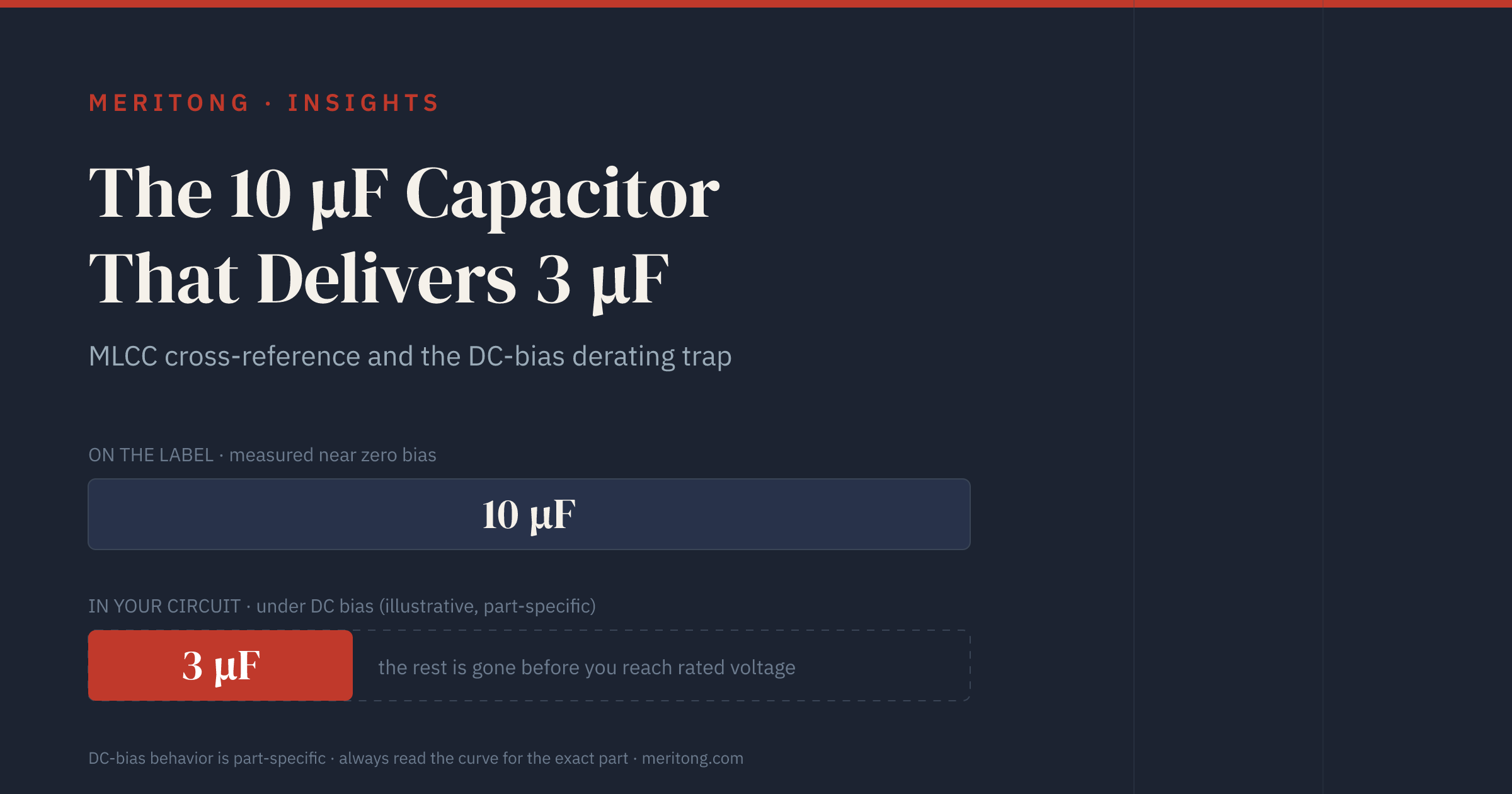
Two properties that a parametric search does not expose govern how much of the marked value a same-value multilayer ceramic capacitor (MLCC) actually delivers: the dielectric class, and the effective capacitance the part still holds at the DC voltage the circuit applies across it. Match the class first, then compare candidates under that bias rather than on the datasheet's front-page value.
You second-source a 10 µF, 0805, 25 V ceramic capacitor, a parametric search returns another 10 µF, 0805, 25 V part, and the two agree on every field the search exposes. In the circuit they need not agree at all, because the capacitance of a Class-2 ceramic falls as DC voltage is applied across it, the fall continues while the part is still below its rated voltage, and how far it goes depends on the dielectric class and on the case size.
One qualification governs everything below. Every figure here belongs to the part and the document named beside it. The fall from 10 µF to 3 µF illustrates the mechanism and measures no particular capacitor; the number for your part comes only from that part's own capacitance-versus-DC-bias curve.
What to check before you approve the swap
| Issue | What can fail | When it matters | Owner | Required verification |
|---|---|---|---|---|
| Dielectric class differs | Temperature window and DC-bias behavior both change at the same marked value | Any substitution chosen on value, voltage and case size alone | Hardware / analog design | Read the class code on both datasheets; match class to class |
| Effective capacitance at the applied bias | Capacitance falls below what the design assumed while the part still measures correctly at zero bias | Class-2 parts run at a meaningful fraction of rated voltage | Hardware design | Read both candidates at the operating voltage in the manufacturer's DC-bias tool |
| Case size reduced at the same value and rating | More capacitance lost to the same bias, since the larger case has thicker dielectric layers and lower dielectric constant materials and loses less | Footprint reductions and cost-down substitutions | Hardware design / layout | Compare both case sizes on their curves at the operating voltage |
| Rated-voltage headroom reduced | Loss grows as the applied voltage approaches the rating | A cheaper alternate with a lower rating on the same rail | Procurement with hardware design | Match or exceed the original's headroom, then confirm on the curve |
| Class-1 position filled with a Class-2 part | Timing, filter or precision behavior drifts with temperature and voltage | C0G / NP0 positions in oscillators, filters, precision analog | Analog design | Confirm the original's class before accepting a Class-2 candidate |
| Temperature range assumed from the class code | The series is qualified over a narrower range than the code permits | Products working near the limits of the class code | Hardware / qualification | Read the range printed in that series' own datasheet |
The dielectric class is the first property to match
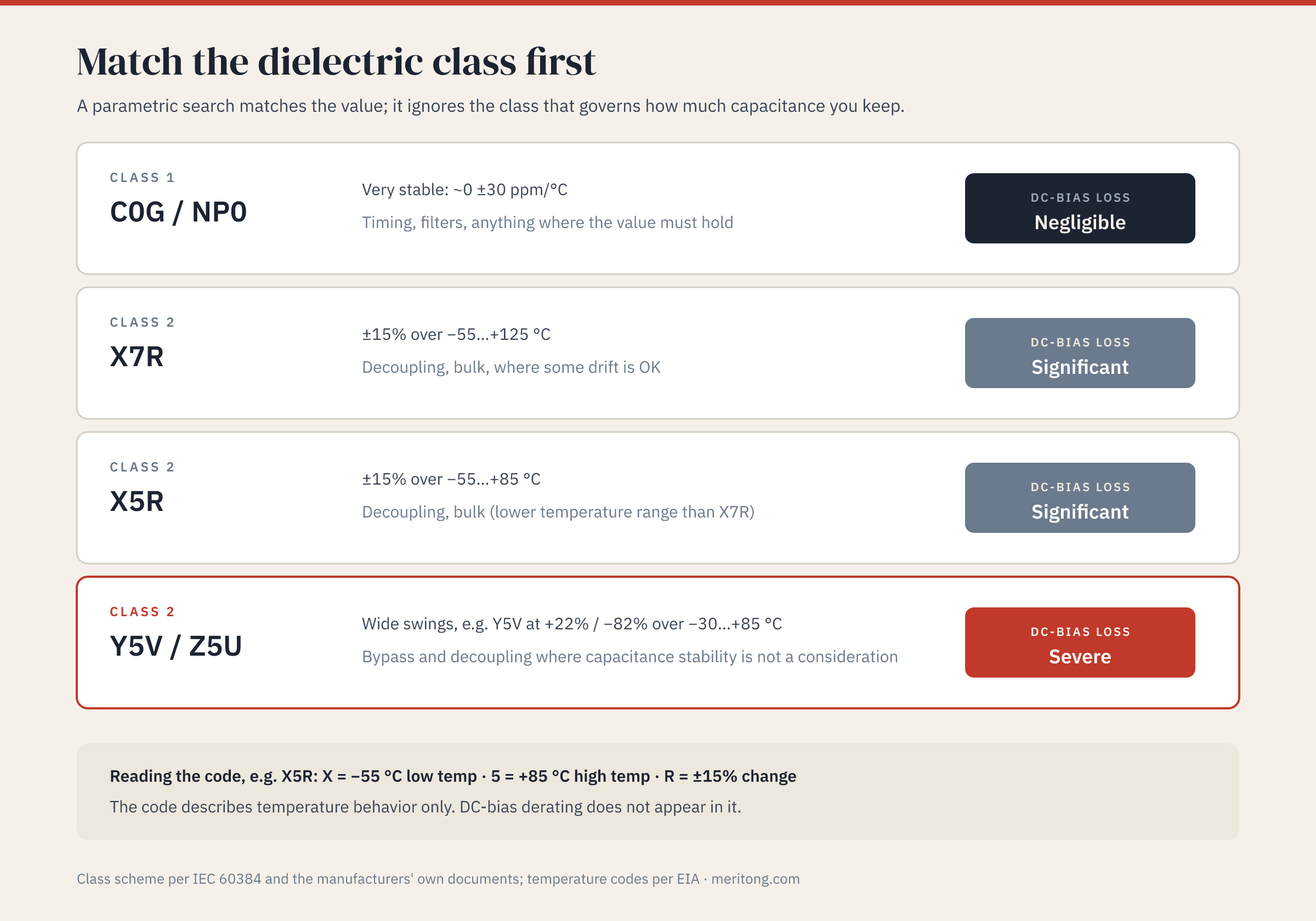
Ceramic dielectrics are grouped into classes, and the class is the first property to match, because it governs both the temperature behavior and whether DC-bias loss arises at all.
| Class / code | Behavior | DC-bias loss | Use it for |
|---|---|---|---|
| Class 1: C0G / NP0 | Very stable, approximately 0 ±30 ppm/°C | Negligible | Timing, filters, anything where the value must hold |
| Class 2: X7R | ±15% over −55…+125 °C | Significant | Decoupling, bulk, where some drift is OK |
| Class 2: X5R | ±15% over −55…+85 °C | Significant | Decoupling, bulk (lower temperature range than X7R) |
| Class 2: Y5V / Z5U | Wide swings, e.g. Y5V at +22% / −82% over −30…+85 °C | Severe | Bypass and decoupling where capacitance stability is not a consideration |
The three-character code is a marking system rather than a description of any one part. It comes from the EIA standard for ceramic dielectric capacitors, the industry scheme that fixes these temperature-characteristic codes, issued as RS-198 and now designated EIA-198-1-F, published by the Electronic Industries Alliance in November 2002 and today maintained by the Electronic Components Industry Association (ECIA). KEMET reproduces the code table verbatim in section 4.1 of F9000_K.pdf, "General Information — Ceramic Capacitors," a document cited here for that table and not for currency: its page footers read 01/2005 and 01/2007 and it still shows Arcotronics branding, though it remains live on KEMET's own content server, checked 27 July 2026. For X5R, "X" fixes the lower category temperature at −55 °C, "5" fixes the upper at +85 °C, and "R" admits a ±15% capacitance change across that range.
Two limits of the code matter here. It describes temperature behavior only, and the voltage behavior this article is about appears nowhere in it. It also states the envelope the marking permits, whereas a given part can be specified more narrowly. KEMET's document gives NP0 as ±30 ppm over −55 to +85 °C in its own worked example, while Murata's SimSurfing measurement-conditions document of 13 September 2022 prints C0G as −55 to +125 °C at 0 ±30 ppm/°C. The two documents describe different scopes, which is why the temperature range you design to comes from the exact series' datasheet. That same Murata table prints X5R's lower bound as −25 °C, where the EIA code letter X is defined as −55 °C and Murata's own reference sheet for the GRM21BR61E106KA73 states an operating range of −55 to +85 °C; the figures above follow the code table and that reference sheet.
The vocabulary needs one note, because catalogues differ on where Y5V and Z5U belong. The table above follows the two-class scheme of the international IEC 60384 sectional specifications for ceramic capacitors, which run Class 1 in Parts 8 and 21 and Class 2 in Parts 9 and 22, all in their 2024 editions. The manufacturers cited here use the same scheme: KEMET states that "ceramic capacitors can be divided into two classes" and offers "X7R, Y5V, Z5U" as its Class 2 examples, and Murata's GRM tutorial states that "for MLCC, there are 2 classes of Temperature Characteristics." The EIA standard draws the line elsewhere. Titled "Ceramic Dielectric Capacitors Classes I, II, III and IV," EIA-198-1-F assigns temperature characteristics A through S to Class II and defines Class III as "identical to that of class II, except that it is restricted to those capacitors having temperature characteristics T through V," which puts Y5V and Z5U in a class of their own. A catalogue that labels a Y5V part "Class 3" is applying the EIA scheme, so take the class from the manufacturer's document for the part in front of you.
What DC bias does to a Class-2 ceramic
Murata sets out the mechanism in its own documentation. In a Class-2, high-dielectric-constant ceramic, applied DC voltage rearranges the spontaneous polarization of the barium-titanate dielectric along the field, and once that rearrangement saturates the dielectric constant falls and takes the effective capacitance with it. Murata states the consequence in a standing caution about high-dielectric-constant capacitors that appears across its reference sheets, unrelated parts included. One of them is GRM21BR61E106KA73-01A, whose specifications Murata dates 25 July 2025 and which covers the exact combination the title uses, a 10 µF, 25 V-rated X5R part in the 0805 case: "In the DC voltage characteristics, the rate of capacitance change becomes larger as voltage increases, even if the applied voltage is below the rated voltage." Murata's phrase "rate of capacitance change" names the percentage change in capacitance, and the company's own technical article "The voltage characteristics of electrostatic capacitance" plots that quantity against DC bias in its Figure 1, captioned "Capacitance change rate vs. DC bias characteristics of various capacitor types (Example)." The loss therefore begins well below the rating, and the percentage of nameplate capacitance lost is larger the higher within its range the part is operated. Two design consequences follow.
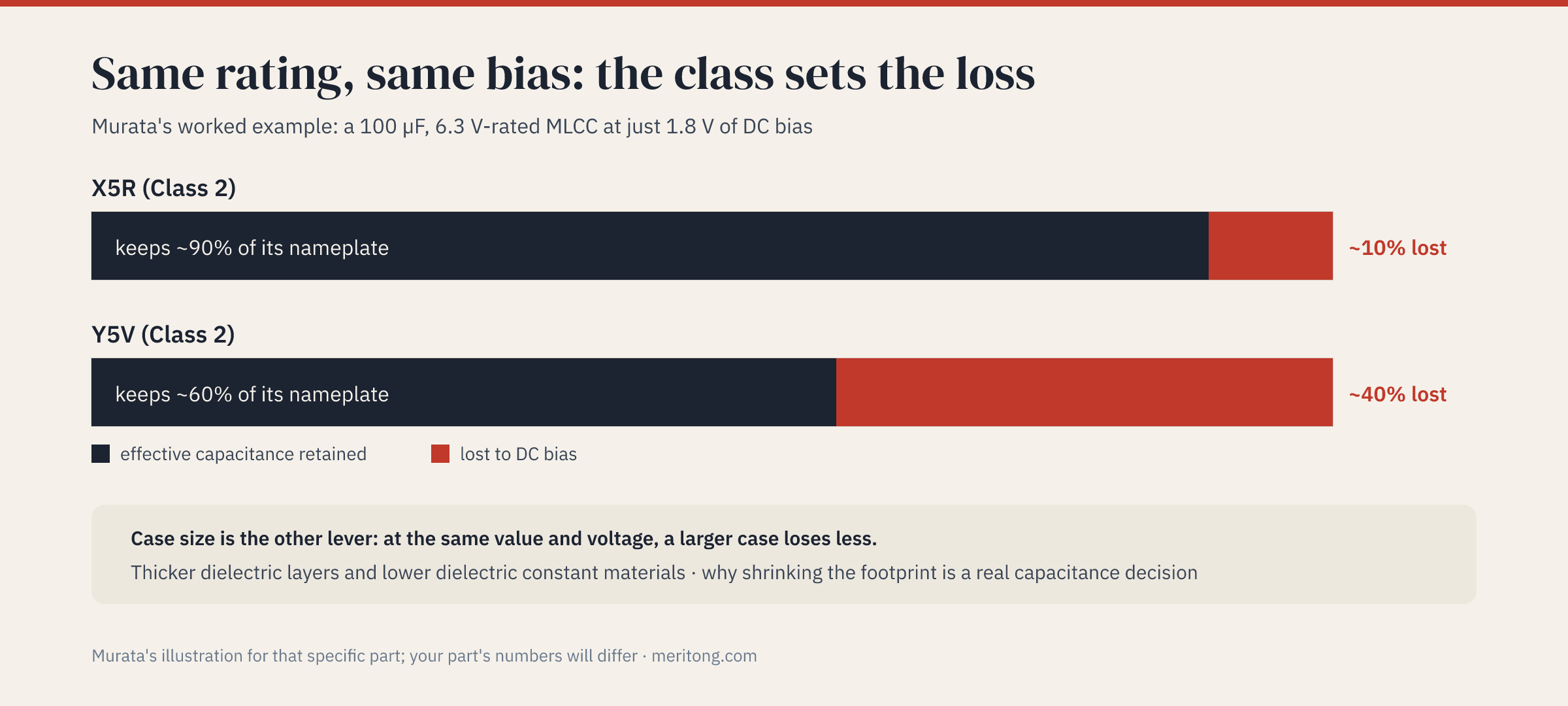
The magnitude depends on the dielectric class: that same article, dated November 28, 2012, works a numeric example. Applying 1.8 V of DC to a high-dielectric-constant MLCC of 100 µF nameplate capacitance and 6.3 V rated voltage, a part with X5R temperature characteristics loses approximately 10% of its capacitance and delivers about 90 µF, while a part with Y5V characteristics at the same bias loses approximately 40% and delivers about 60 µF. Those figures belong to Murata's own example, a 100 µF, 6.3 V part at 1.8 V, and they do not transfer to the 10 µF, 25 V part in the title. What transfers is the ordering: at the same bias, the class changes the size of the loss.
The magnitude depends on the case size: Murata's "High Capacitance MLCC — GRM Series Product Tutorial" of October 28, 2020 states that "for Class II capacitors (X5R, X7R, etc.), the larger case size components have less capacitance change versus DC Bias voltage due to thicker dielectric layers and lower dielectric constant materials." The chart on that slide compares 0603, 0805 and 1206 parts of the same 10 µF value in X5R, with DC bias swept from zero to the rated voltage. At the same rated capacitance and voltage, moving to a smaller case therefore costs capacitance under bias. Shrinking the footprint is a capacitance decision as well as a board-space one.
Together they make the title's scenario plausible as an illustration: a small-case, high-value Class-2 part run at a meaningful fraction of its rated voltage can deliver a fraction of its nameplate value in a decoupling network that measured correctly at zero bias. Murata draws the practical conclusion itself: "when selecting multilayer ceramic capacitors, the electrostatic capacitance noted in the catalog should not be accepted without question. Instead, it is necessary to measure the electrostatic capacitance while applying the DC voltage component of the power supply (signal) line where the capacitor is to be used, and understand the effective capacitance value."
How to cross-reference an MLCC correctly
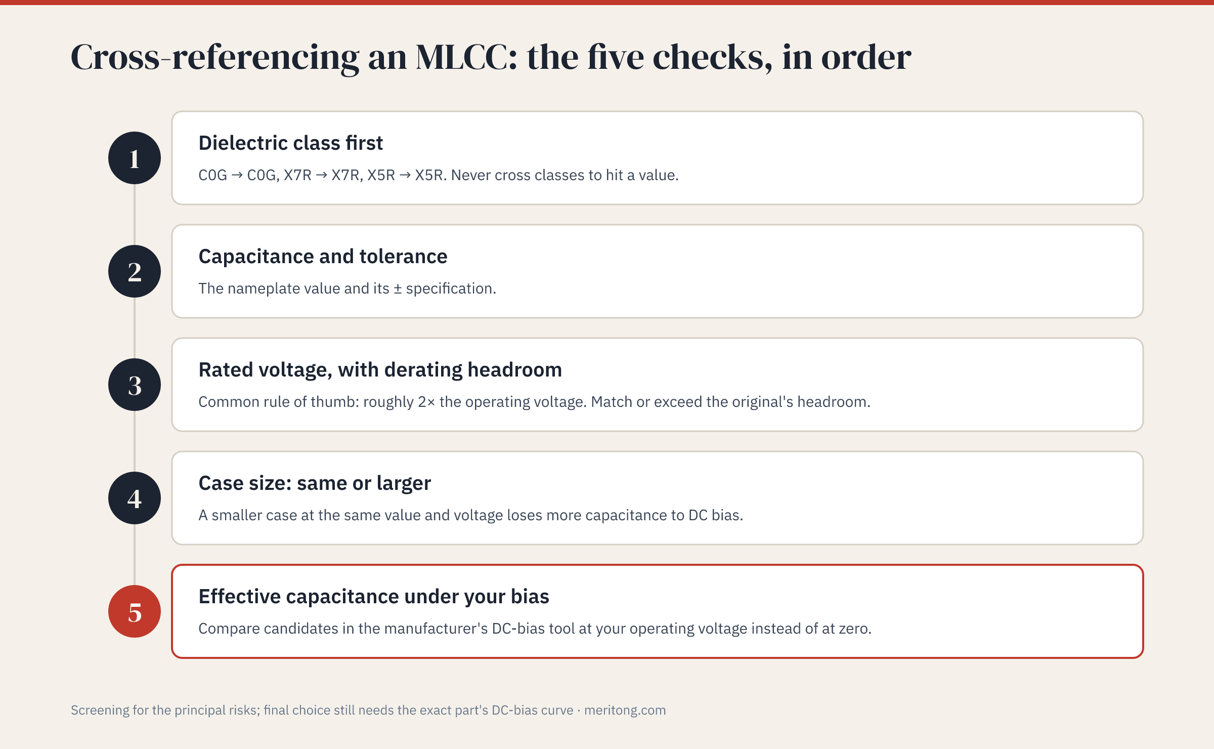
The five checks below are this article's synthesis of what the manufacturer documentation requires, and no single manufacturer publishes them as a list. They screen for the principal risks in a substitution. They do not qualify a part: that decision still rests on the exact orderable part number, its own datasheet and DC-bias curve, and the behavior of the assembled circuit.
Dielectric class first: C0G to C0G, X7R to X7R, X5R to X5R. Never cross classes to reach a value. Where the original is a Class-1 C0G part in a timing or filter position, a Class-2 substitute changes the behavior the circuit was designed around.
Capacitance and tolerance: the nameplate value together with its ± specification, since the admissible capacitance change is a property of the class code and two parts marked 10 µF need not hold the same tolerance band.
Rated voltage, with derating headroom: capacitance falls as the applied voltage approaches the rating, so a rating well above the operating voltage preserves more of the value. A common rule of thumb puts it at roughly twice the operating voltage. Match or exceed the headroom the original had.
Case size, same or larger: at the same value and rated voltage, a smaller case loses more capacitance to the same bias, for the reason Murata's tutorial gives. A candidate that saves board area at constant value and voltage is a capacitance reduction the parametric fields do not display.
Effective capacitance under your DC bias: compare the candidates where the circuit will run them. Murata's SimSurfing, a free web-based design-support tool, displays capacitance-versus-DC-bias characteristics for parts in Murata's own catalog, and TDK publishes a downloadable DC Bias Model, announced on 8 July 2014, whose simulated capacitance changes as the simulated bias voltage changes. Read both candidates at the operating voltage instead of at zero, and take the one that still holds the capacitance the circuit needs there. A parametric comparison cannot perform this step, because the nameplate value is specified at or near zero bias.
Skip the first or the last and the decision rests on the marking, which is the one property the two parts were already known to share.
A worked cross-reference
Take an original of 10 µF, 0805, 25 V, X7R, decoupling a 12 V rail, which has gone end-of-life.
Class: the candidate needs to be X7R, or a Class-2 dielectric whose limits you have checked against the application. An X5R part at the same value and rating stops at +85 °C where X7R continues to +125 °C, so it is a candidate only where the product never exceeds 85 °C. A "10 µF 0805 25 V" that turns out to be Y5V brings a +22% / −82% window over −30 to +85 °C, and in Murata's example on a different part the Y5V version lost approximately 40% where the X5R version lost approximately 10% at the same bias. TDK states in its own FAQ that it "no longer offers MLCCs in Y5V or Z5U temperature characteristics," so a Y5V in a 2026 parametric result came from elsewhere in the market.
Value, tolerance and voltage: 10 µF at the original's tolerance band, and a 25 V rating against a 12 V rail gives roughly the 2× headroom the rule of thumb asks for. Keep it. A cheaper 16 V-rated alternate reduces that headroom and will hold less of its 10 µF at 12 V.
Case size: 0805 or larger. At the same value and rated voltage, a smaller case loses more capacitance to the same DC bias, for the two reasons Murata gives: the larger case has thicker dielectric layers and lower dielectric constant materials. Where a 0603 candidate is offered at all at this value and rating, what it saves in board area it gives up in capacitance under bias, so read both case sizes on their curves before taking the saving.
Under-bias check: pull both parts into the manufacturer's DC-bias tool and read them at 12 V. The candidate that still holds the capacitance the rail needs there is the one worth qualifying; the candidate that reads 10 µF at zero bias and materially less at 12 V is the failure this article is about.
The exercise converts a nameplate match into a comparison of the values the circuit will actually see. It remains screening: the decision to build is made on the exact orderable part number, at the temperature range that part's datasheet states, and on the assembled board.
Reading the DC-bias data before you commit
Obtain the current datasheet for the exact orderable part number of the candidate, suffix included, and read the dielectric class and the temperature range it states for that series. Obtain the same for the part being replaced. Then open the manufacturer's DC-bias data for both, through SimSurfing for Murata parts or TDK's DC Bias Model for TDK parts, and read effective capacitance at the DC voltage of the rail the capacitor will run on. Murata's own instruction goes further and asks the designer to measure capacitance with the line's DC voltage component applied, so where the rail's behavior under load matters, close the loop on the assembled board.
The curve will not tell you whether the tolerance band and the temperature range of the candidate match the original, both of which appear in the datasheet rather than in the tool, and a manufacturer's tool covers only that manufacturer's catalog. The manufacturers are explicit about the limits of their matching tools: TDK's MLCC cross-reference page, which accepts competitor part numbers and returns TDK equivalents, states that "the displayed search result has no guarantee that it is compatible with other companies products."
FAQ
What's the difference between X7R and X5R?
Both are Class-2 dielectrics admitting the same ±15% capacitance change, and both are subject to the DC-bias loss described above. The code differs on the upper temperature limit: X7R runs to +125 °C, X5R to +85 °C. Above 85 °C an X5R part is no substitute for an X7R part. Confirm the range in that series' own datasheet, since a series can be qualified more narrowly than its code permits.
Why does my 10 µF capacitor measure much less in-circuit?
DC-bias derating is one likely explanation. A Class-2 ceramic (X5R, X7R and similar) loses effective capacitance as DC voltage is applied, and Murata's reference sheets for such parts state that the percentage change in capacitance is larger at higher voltage while the part is still below its rating. The nameplate is specified at or near zero bias, so the in-circuit value is lower, and the deficit is larger for small-case, high-value parts. Ageing is a second mechanism: the same Murata reference sheet records that high-dielectric-constant capacitors lose capacitance with the passage of time, and KEMET's section 4.5 notes that soldering heat restores the value and restarts the process. Temperature and measurement conditions also move the reading, so confirm against the part's own curve.
Is C0G / NP0 affected by DC bias?
It is essentially unaffected. Murata's SimSurfing measurement-conditions document states that capacitors for temperature compensation, the C0G type among them, "hardly change when DC bias voltage is applied," and that SimSurfing does not plot DC-bias effects for them for that reason. Class-1 dielectrics are therefore specified where the value has to hold, in timing, filtering and precision positions. The trade-off is that they are practical only at smaller capacitances, which is why decoupling and bulk positions use Class-2 parts.
Can I just use a bigger case size to fix DC-bias loss?
It helps, for the reasons Murata's GRM series tutorial gives: at the same rated capacitance and voltage, a larger case has thicker dielectric layers and lower dielectric constant materials, and loses less capacitance to the same bias. Confirm the improvement on that part's curve instead of assuming it, and weigh the board area and cost a bigger footprint brings.
Do parametric search tools protect me from this?
They do not, and one manufacturer says so on its own tool page. A parametric filter matches the value, the rated voltage and the case size, none of which expresses effective capacitance at your bias. TDK's MLCC cross-reference tool, which takes competitor part numbers and returns TDK equivalents, disclaims any guarantee that the results are compatible with other companies' products. Such a tool produces candidates; the DC-bias curve decides whether a candidate is real.
Do aluminum electrolytic or tantalum capacitors have this problem?
Murata describes the phenomenon as "peculiar to high dielectric constant-type multilayer ceramic capacitors that use barium titanate-based ferroelectrics," and names the technologies where it "does not occur much at all": conductive polymer aluminum electrolytics, conductive polymer tantalums, film capacitors, and temperature-compensating-type multilayer ceramic capacitors. Aluminum electrolytics and tantalums outside those polymer families are not covered by that sentence, so confirm the behavior in the candidate's own datasheet. All of these alternatives bring constraints of their own, among them equivalent series resistance (ESR), physical size and service life. Cross-referencing a Class-2 ceramic to another capacitor technology is a larger change than a like-for-like MLCC substitution, and it deserves a review by whoever owns the analog design.
How much capacitance headroom should I design in?
Enough that the effective capacitance under bias still meets the requirement, which is why the curve rather than the nameplate is the number to design to. Over-specify both the value and the voltage rating so that margin survives derating, and take the amount from the part's own curve at the operating voltage. No general multiplier substitutes for that lookup, because the curve differs by class, case size and rated voltage.
The verdict
Second-sourcing a ceramic capacitor is one possible response to an end-of-life notice, a price move or an allocation problem, and it deserves a balanced verdict. In its favor, the check is cheap: the documents are public, and the manufacturers publish the curves themselves. A class-correct alternate that still holds its capacitance at the operating voltage, once qualification confirms it, turns an end-of-life notice into a purchase order. Against that, such an alternate may need a larger case or a higher voltage rating, at a cost in board area and unit price; the check has to be repeated for every rail and every bias condition rather than once per line of the bill of materials; and each substitution adds a supplier the design then depends on. Whether it pays depends on the volume, the temperature range the product must meet, the board area available, and how much capacitance the circuit had to spare.
The discipline underneath does not depend on any of those variables. The capacitance a Class-2 ceramic delivers is a function of the voltage across it, the parametric fields do not express that function, and the manufacturers publish it for anyone who looks.
A Second-Source Map cross-references the ceramic capacitors on your bill of materials on that basis. It matches dielectric class instead of the nameplate value alone, compares effective capacitance at the bias each part actually sees, and names what still has to be confirmed on your own hardware. If that would help, that is what I do.
This article explains a real, part-specific phenomenon with illustrative figures, drawn from the documents named: Murata's technical article "The voltage characteristics of electrostatic capacitance" (November 28, 2012), which states that its information was current as of publication and may differ from the latest; Murata's SimSurfing measurement-conditions document (13 September 2022); Murata reference sheet GRM21BR61E106KA73-01A (specifications dated 25 July 2025; Murata directs the reader to its approval sheet before ordering); the "High Capacitance MLCC — GRM Series Product Tutorial" (October 28, 2020); KEMET F9000_K.pdf (page footers 01/2005 and 01/2007); TDK's DC Bias Model, MLCC cross-reference page and temperature-characteristics FAQ; and, for the class schemes, EIA-198-1-F (November 2002) and IEC 60384-8, -9, -21 and -22 (2024 editions). All were checked on 27 July 2026. It is general engineering guidance and does not specify any particular capacitor. Datasheet revisions change, so re-read the current revision for the exact part you are substituting, and verify effective capacitance against the manufacturer's DC-bias data for that part.
Get the next pattern by email
One dependency pattern from real hardware audits, occasionally. No schedule promised yet.
Working through this right now? Book a call → or write to me →