Components
Crystals & Oscillators: Load Capacitance, Drive Level, and Why Your Oscillator Won't Start
A crystal oscillator needs two things to start and run on frequency: the load capacitance the crystal was adjusted for, and enough gain margin to overcome its losses. ST's AN2867 recommends a margin of at least 5; a second-sourced crystal that drops below that line produces a dead oscillator, an intermittent start, or a clock off frequency, and this article works through the four numbers that decide it.
Last updated: October 2026. The formulas come from ST's oscillator design guide AN2867 (Rev 24, February 2026). The cross-checks come from the NXP, ECS, Abracon and Statek documents named in the text at the revisions given there. All were checked on 21 October 2026. Verify every value against your own crystal's datasheet and your MCU's oscillator section before you commit a design.
The short version
A crystal oscillator needs two conditions to start and to run on frequency. The circuit has to present the load capacitance (CL) the crystal was adjusted for. The oscillator has to supply enough gain to overcome the crystal's losses, with a safety margin. STMicroelectronics' (ST's) oscillator design guide, AN2867, says startup problems "usually arise because the gain margin is not properly dimensioned". It names two causes: load capacitors that are too small or too large, and an equivalent series resistance (ESR) that is too high.
A failure takes one of three forms: a dead oscillator, an intermittent start, or a clock off frequency. An offset becomes a fault once it exceeds the tolerance of what the clock drives, such as USB, a Controller Area Network (CAN) link or a real-time clock.
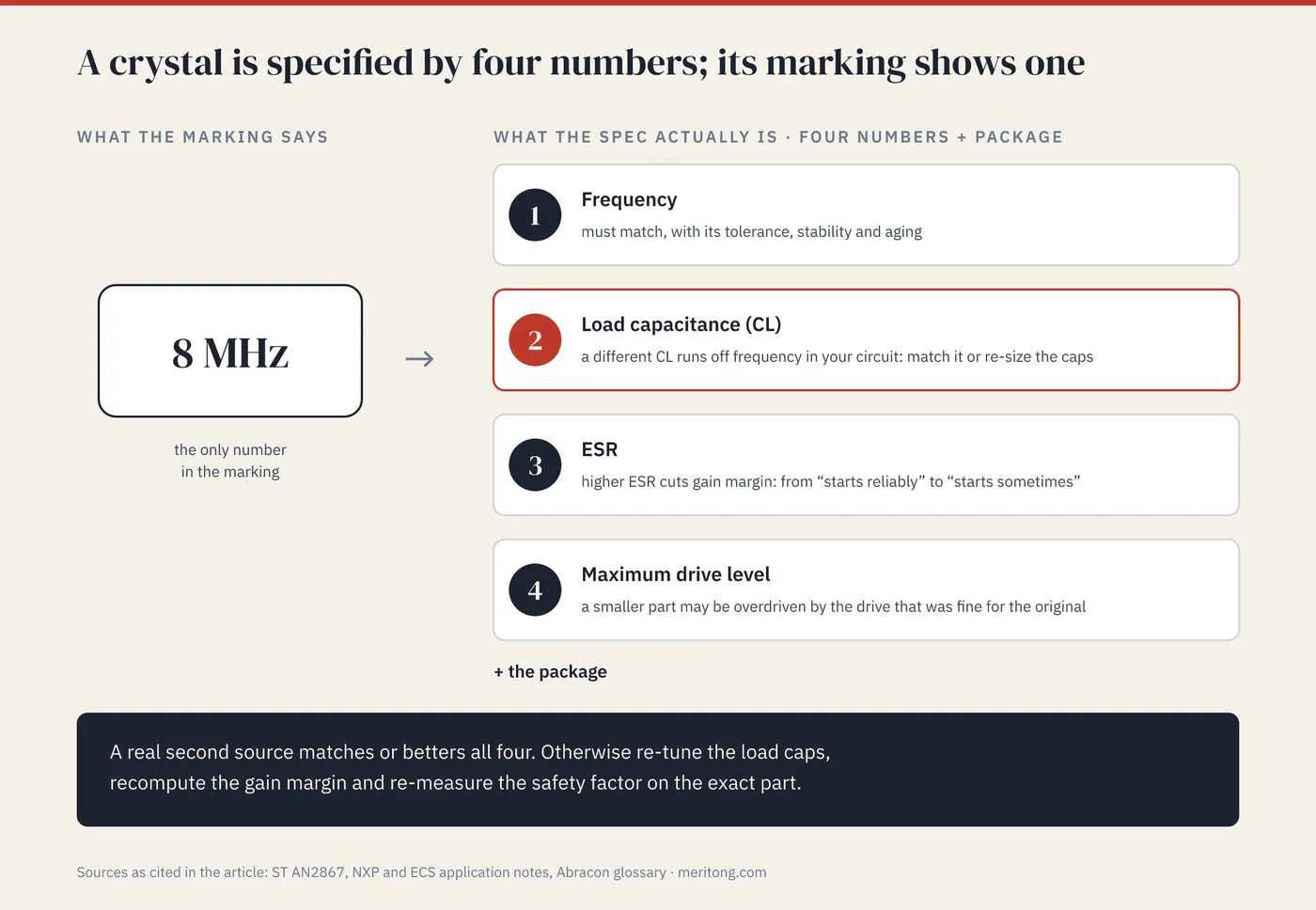
The marking on a crystal states its frequency, and the frequency is only part of the specification. Two 8 MHz crystals in the same package can have different load capacitances, ESR values and drive-level limits. Exchanging one for the other without checking those three can move the frequency or stop the oscillator from starting.
The datasheet gives the three numbers the marking leaves out. CL is the load at which the marked frequency is delivered; ESR is the loss the oscillator must overcome. The maximum drive level limits the power the crystal may dissipate. The load capacitors couple the first two: the capacitance that puts the crystal on frequency also enters the gain needed to start, so a change to them moves both.
| Datasheet number | What fails if it is wrong | Where the risk is highest | What to verify |
|---|---|---|---|
| Load capacitance (CL) | The clock runs off frequency | Low-CL crystals, where a picofarad of error moves the frequency furthest | Load caps sized from CL; frequency measured on several boards |
| ESR | The oscillator starts late, intermittently or not at all | Gain margin close to AN2867's recommended 5; 32.768 kHz crystals | Gain margin computed from the microcontroller and crystal datasheets |
| Maximum drive level | The crystal is overdriven and ages faster or drifts | Watch crystals, whose limits can be below 1 µW | Drive level measured on the board; series resistor added if needed |
The load-capacitance formula
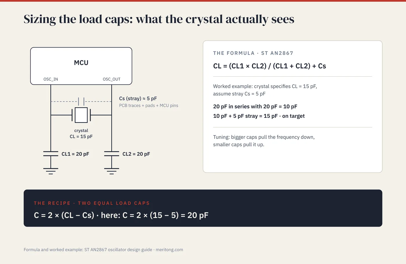
A crystal is specified to run at its marked frequency when the circuit presents a particular load capacitance, its CL. ST's oscillator design guide AN2867 (Rev 24, February 2026) defines the load the oscillator circuit presents in Section 3.3:
the load capacitance is the terminal capacitance of the circuit connected to the crystal oscillator … CL = (CL1 × CL2)/(CL1 + CL2) + Cs
Here CL1 and CL2 are the two external load capacitors, one from each crystal pin to ground. Cs is the stray capacitance, which AN2867 defines as the sum of the microcontroller's (MCU's) oscillator pin capacitance and the parasitic capacitance of the printed circuit board (PCB). All of it adds to the load the crystal sees. AN2867 works an example: for a crystal that specifies CL = 15 pF, assuming Cs = 5 pF, you get CL1 = CL2 = 20 pF.
The example contains the whole sizing method. The two external caps are in series as far as the crystal is concerned, because both paths go to ground. Their series combination is CL1·CL2/(CL1+CL2), which for two equal 20 pF caps is 10 pF. Add the 5 pF of stray and you land on the crystal's specified 15 pF. Match that value and the crystal runs at the frequency it was adjusted for; miss it and the frequency moves.
Sizing your load caps
Turned around, the formula becomes a recipe. The worked examples in AN2867 and in ECS's load-capacitance article both use two equal load caps, and with each one called C:
CL = C/2 + Cs, so C = 2 × (CL − Cs).
The method takes three steps.
Read CL off your crystal's datasheet. It will be a number such as 8 pF, 12 pF, 18 pF or 20 pF. The value is fixed, because it is the load the crystal was trimmed to.
Estimate Cs, the stray capacitance. ECS's design note Oscillator Design Basics (page updated 14 January 2025) gives 3 to 5 pF as the usual range, and AN2867's example uses 5 pF. Where your MCU's datasheet gives an oscillator pin capacitance, use it and add an estimate for the board. If the figure is per pin, two equal pins add about half of it to CL, because the crystal sees them in series. If the datasheet gives no pin capacitance, start from 5 pF and treat it as an estimate until the bench confirms it.
Compute each external cap: C = 2 × (CL − Cs).
The worked examples below all use Cs = 5 pF, and the last column gives the nearest values in the E12 preferred-number series of IEC 60063:
| Crystal CL | Each load cap C = 2 × (CL − 5 pF) | Nearest E12 value |
|---|---|---|
| 8 pF | 6 pF | 5.6 pF |
| 12 pF | 14 pF | 15 pF |
| 15 pF | 20 pF | 18 or 22 pF |
| 18 pF | 26 pF | 27 pF |
| 20 pF | 30 pF | 27 or 33 pF |
Two consequences follow from the table, and the first is that an 8 pF crystal needs small external caps. With 5 pF of stray, only about 6 pF is left for each cap, and a careless layout can consume that budget. Statek's Technical Note 33 (Rev. A) adds that a crystal "is more sensitive to [a] given change in CL at lower values of CL". An error in the stray estimate therefore moves the frequency most in the low-CL rows.
Second, standard capacitor values are coarse, so frequency is tuned by nudging these caps. The direction is fixed: bigger caps pull the frequency down, and smaller caps pull it up. A board that runs slightly fast on 18 pF caps moves down when they become 22 pF.
The same capacitors appear again in the condition for starting, so every tuning step also changes the gain margin.
Why your oscillator won't start: gain margin
Sizing the caps puts the crystal on frequency. Startup is a separate question, and it turns on whether the oscillator can produce enough gain to overcome the crystal's losses.
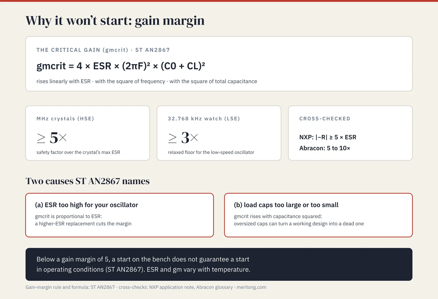
Every crystal has an ESR, the loss it presents at resonance. The oscillator has to supply enough "negative resistance", which is to say active gain, to cancel that loss with room to spare. Otherwise the oscillation never builds up. AN2867 formalizes this as a gain margin, the oscillator's transconductance (gm) divided by the critical gain (gmcrit). The critical gain is the transconductance needed just to sustain oscillation. Section 3.4 states one threshold and sets no separate one for the low-speed oscillator:
it is highly recommended that the selected crystal has a gain margin higher than or equal to 5
where the critical gain is
gmcrit = 4 × ESR × (2πF)² × (C0 + CL)²
with C0 the crystal's shunt capacitance, which AN2867 attributes to the capacitor formed by the electrodes. The critical gain (gmcrit) rises with ESR, with the square of frequency and with the square of the total capacitance C0 + CL. An ESR too high for the oscillator raises gmcrit directly, and load caps that are too large raise it through the capacitance term. Caps that are too small are on AN2867's list as well. For STM32F0 and STM32F3 parts, Section 4.1 restricts the high-drive mode to 12.5 pF crystals to avoid saturating the oscillation loop.
The capacitance term is the same lever the previous section used for tuning. Oversize the load caps and the frequency shifts, while the gain the oscillator needs in order to start rises as well. That second effect can turn a working design into a dead one.
AN2867 states the requirement a second way, as a safety factor. The safety factor is the oscillator's negative resistance divided by the crystal's ESR, measured on the bench with an added series resistor. Here AN2867 does distinguish the oscillator types, asking for at least 5 on the high-speed external (HSE) oscillator that drives MHz crystals. On the low-speed external (LSE) oscillator for 32.768 kHz crystals, it asks for at least 3.
Other vendors set the same floor. NXP's Crystal Oscillator Design Guide AN14518 (Rev. 6.0, 17 April 2026) is written for its near-field communication (NFC) reader circuits. It gives the criterion as |−R| ≥ 5 × ESR. ECS's design note recommends a negative resistance of at least five times the crystal's maximum ESR. Abracon's undated Quartz Crystal Glossary of Terms recommends "at least 5 to 10 times" the ESR.
A design below the recommended margin may still start on the bench. AN2867 warns that such a start "does not guarantee that the oscillation starts in operating conditions". It notes that ESR varies with temperature and moisture, and that transconductance varies with supply voltage and temperature. ECS adds that negative resistance tends to fall at elevated temperature, so it recommends testing at the top of the operating range.
Drive level: the third number
Drive level is the power the oscillator dissipates in the crystal. With too little, a high-ESR crystal may not start reliably, and too much overdrives the crystal. ECS lists unstable operation and accelerated aging, and in some cases complete crystal failure; Abracon's glossary warns of possible long-term frequency drift or crystal fracture. The remedy is an external series resistor on the output (drive) side that limits the current into the crystal. AN2867 calls it RExt and makes it mandatory once the dissipated power exceeds the crystal's rating.
The resistor has a cost at startup, because AN2867 adds RExt to the ESR in the gmcrit formula. The gain margin has to be computed again after the resistor is fitted.
AN2867, NXP's AN14518 and ECS all leave the maximum drive level to the specific crystal's datasheet. The spread between crystal types is wide. ECS's ECX-34Q 32.768 kHz crystal (datasheet Rev. 2022) allows 0.5 µW at most, and its ECX-33Q MHz crystal (datasheet Rev. 2023) allows 100 µW. A single "safe" drive number quoted without your crystal's datasheet is a guess.
What this means for a second source
Cost-down or supply-resilience work on a China-sourced bill of materials (BOM) may swap a crystal because the original is on allocation or a distributor offers a cheaper part. Matching the frequency and the package leaves three of the crystal's specifications unchecked, and nothing obliges them to match because the marked frequency does. NXP's AN14518 states the rule for a different crystal: "frequency accuracy, drive level, nominal load capacitance, and ESR must be carefully selected according to the specification provided in each product data sheet".
Load capacitance: a crystal with a different CL runs off frequency in your circuit, because your load caps were sized for the original CL. A 12 pF part on a board built for an 18 pF part runs low, because it sees more load than it was adjusted for. Either match CL or re-size the load caps.
ESR: a replacement with higher ESR consumes gain margin. In AN2867's formula gmcrit is proportional to ESR, so twice the ESR halves the margin when gm, frequency and capacitance stay unchanged. That change can move a design from "starts reliably" to "starts sometimes".
Drive level: a physically smaller or lower-power replacement may have a lower maximum drive level, so the drive that was fine for the original now overdrives the substitute.
Statek's Technical Note 33 (Eq. 4) gives the frequency shift caused by a change in CL. It computes the shift from the crystal's motional capacitance (C1) and shunt capacitance (C0), which some datasheets list. ECS lists typical values of 3.5 fF and 1.1 pF for its ECX-34Q watch crystal. The part is offered at 6, 7, 9 and 12.5 pF. On those values, a 7 pF version on a board built for the 12.5 pF version runs about 87 ppm low. That is roughly 7.5 seconds a day, against the datasheet's ±20 ppm tolerance at 25 °C.
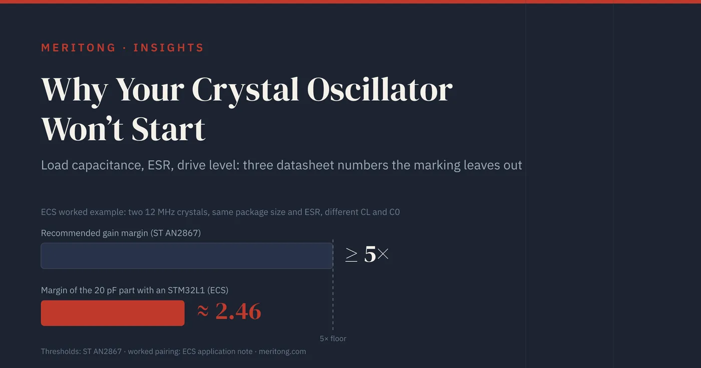
A CL change reaches startup as well. In The Impact of Load Capacitance on Crystal Oscillator Designs (23 January 2025, updated 28 April 2025), ECS compares two of its 12 MHz crystals. They share the package size and an ESR of 100 Ω and, in ECS's words, "have different C0 and CL values". ECS-120-20-33-AEL-TR is specified at 20 pF and ECS-120-8-33B-CHN-TR at 8 pF. With the STM32L1, whose HSE transconductance ECS gives as 3.5 mA/V, the 20 pF part has a margin of only 2.46. The 8 pF part reaches 12.72. Part of that gap comes from the shunt capacitance. Back-calculated from ECS's gmcrit figures, C0 is about 5 pF for the 20 pF part and 3 pF for the 8 pF part. With C0 held at 5 pF, the 8 pF part would reach about 9.1. ECS adds that "[w]hile oscillation might start, the design would lack robustness".
A crystal can still be second-sourced on these terms. On the BOM it is four numbers plus the package: the marked frequency with its tolerance, stability and aging, and the three datasheet numbers above. A real second source matches or betters all four. Otherwise the load caps are re-tuned, the gain margin recomputed and the safety factor re-measured on the bench. Each of the four can be checked against datasheets before the order is placed. A pin-compatible part that fails one of them is no drop-in, and the mismatch can surface later as field returns.
FAQ
My oscillator doesn't start at all. Where do I look first?
AN2867 says startup problems usually come from the gain margin, so check the caps and the ESR first. Size the load caps from the crystal's CL, since caps copied from a reference design suit that design's crystal only. Check that the crystal's ESR leaves a gain margin of at least 5 with your oscillator's gm. Then check for wrong or missing series or feedback components. Finally, check the layout, since long traces to the crystal add stray capacitance and pickup.
My clock runs off frequency. Is the crystal bad?
Check the load first, because a frequency offset is one likely sign that the load your circuit presents does not match the crystal's CL. Recompute C = 2 × (CL − Cs) with a realistic stray estimate. Bigger caps pull the frequency down, and smaller caps pull it up. The crystal's own tolerance, temperature drift and aging add offset too. The ECX-34Q datasheet allows ±20 ppm at 25 °C and ±3 ppm in the first year. Suspect the crystal itself once the load is right.
What stray capacitance (Cs) should I assume?
ECS gives 3 to 5 pF as the usual range, and AN2867's worked example uses 5 pF. The value remains an estimate until you confirm it by measuring the actual frequency on a few boards and trimming the load caps. On a low-CL crystal the stray is a large fraction of CL, so an error in Cs moves the frequency further there.
Can I just use the caps from the reference design?
You can, if you use the exact same crystal with the same CL and package on a similar layout. Reference-design cap values are sized for that reference's crystal and its stray. With a different crystal or a very different layout, size the caps again from C = 2 × (CL − Cs).
Does a bigger load cap make startup more reliable?
It makes startup harder. gmcrit rises with the square of total capacitance, so bigger load caps increase the gain needed to start. Oversizing caps "to be safe" can turn a marginal oscillator into a dead one. AN2867 lists caps that are too small among the causes as well, so size them to hit CL.
How do I know my drive level is safe?
Read the maximum drive level off your crystal's datasheet and stay under it; there is no universal number. Signs of overdrive include unstable operation or frequency drift and accelerated aging, and in the extreme the crystal fails. If you suspect it, add or increase the series resistor on the drive side and measure again. Then recompute the gain margin, because AN2867 adds that resistor to the ESR in gmcrit. The limit is a per-crystal specification, so do not copy a resistor value from one crystal to another.
Do these rules change for a 32.768 kHz watch crystal?
The formulas are the same, and the numbers differ widely. ECS's ECX-34Q watch crystal allows up to 70 kΩ of ESR and 0.5 µW of drive. Its ECX-33Q allows 100 Ω from 10 to 15.999 MHz and 100 µW. AN2867 relaxes the negative-resistance safety factor for the LSE oscillator to at least 3, against at least 5 for HSE. ECS calls poor gain margin "a common problem in kHz oscillators" and says careful design is required to overcome it.
Close
A crystal is specified by four numbers: frequency, load capacitance, ESR and maximum drive level. The frequency comes with a tolerance, a temperature stability and an aging figure, and the marking shows only the nominal value. Size the load caps from the crystal's CL with C = 2 × (CL − Cs). Keep the gain margin of at least 5 that AN2867 recommends, and stay under the datasheet drive level. The first two disciplines share a variable. The capacitance that sets the frequency also enters the gain needed to start, so a change made for one reason is felt in the other.
A second source for a crystal brings supply security and room on price. Its cost is the check of these numbers. Where they differ, the load caps need re-tuning, the gain margin a new calculation and the safety factor a bench check. That check is cheap on paper, and a startup or frequency fault found in the field is expensive to trace.
If a crystal swap leaves you unsure whether the load caps and gain margin still hold, I help with component and product-architecture problems of this kind. I look at hardware, firmware and sourcing together, particularly where parts are sourced from China.
This article quotes ST AN2867 for the load-capacitance and gain-margin formulas and cross-checks NXP, ECS, Abracon and Statek. It is general engineering guidance and does not substitute for your crystal's datasheet, your MCU's oscillator specification, or bench verification of the safety factor and frequency on your actual board.
Typical dependencies by email
Examples from real hardware audits, sent occasionally.
Working through this right now? Free intro call → or write to me →
Is this question on your desk right now?
In the free potential check you tell me the type of components you use. After 30 minutes you know whether an audit is worth it.
Free intro call