Last updated: July 2026. Stability behavior is part-specific. The datasheet figures below belong to the parts named, and you should confirm the output-capacitor requirement for the exact regulator you intend to use.
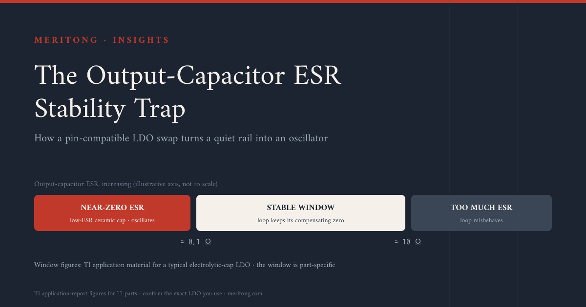
The short version
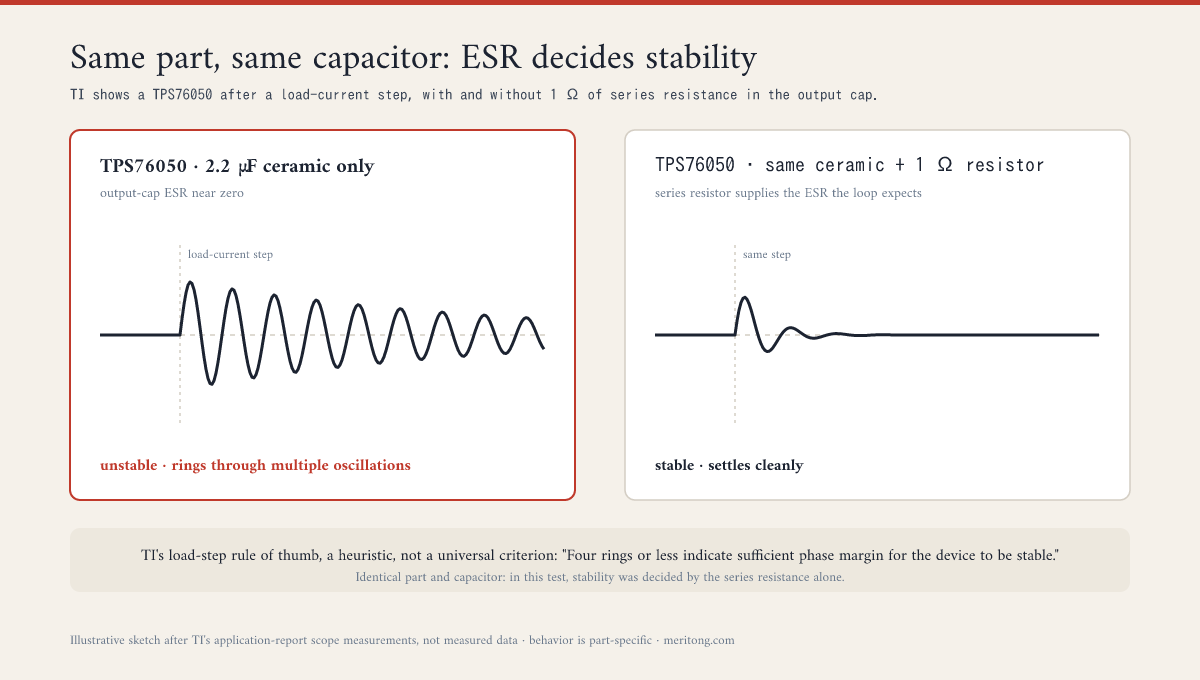
Texas Instruments published this failure as a pair of oscilloscope figures. In its TPS76050 application report (SLVA115A), one trace shows the regulator ringing through several oscillations after a load-current step with a 2.2 µF ceramic output capacitor. The second trace shows the same regulator, the same capacitor and the same step settling cleanly, and the only difference between them is a 1 Ω resistor in series with the capacitor.
Those two traces explain a class of failure that appears after an apparently safe substitution. You replace one low-dropout regulator (LDO) with a pin-compatible one, matching package, output voltage and every field the parametric search exposes, and a rail that used to be quiet begins to oscillate, sometimes hard enough that the symptom looks like a fault elsewhere on the board.
Several specifications can misbehave after such a substitution. Input-capacitor requirements, minimum load, noise-bypass interactions, current-limit behavior and operation near dropout all belong on the list. One common and easily missed cause is the specification usually absent from the comparison table, the output-capacitor requirement, and it is the one that can turn a working design into an oscillator with no code change and no schematic change at all.
The governing principle takes a sentence. An LDO's frequency compensation is split between the silicon and your board, and the datasheet's stability section is where the vendor describes that split. Many LDOs depend on the equivalent series resistance (ESR) of the output capacitor to remain stable. With too little ESR the control loop loses its stabilizing zero and can oscillate, and with too much it can also go unstable. Requirements differ from part to part along a whole spectrum. Some LDOs need ESR inside a bounded window, some are designed for low-ESR ceramics and still impose limits of their own, and some remain stable with almost any capacitor or with none at all. Swap between parts with different requirements while leaving the output capacitor unchanged, and you can drive the loop unstable.
One qualification governs everything below. Every number here belongs to the document and the device named beside it. None of them transfers to another vendor's LDO, and none replaces the stability section of the datasheet in front of you.
What to check before you approve the swap
| Issue | What can fail | When it matters | Owner | Required verification |
|---|---|---|---|---|
| Output-capacitor ESR or capacitance requirement differs | Loop loses phase margin; rail rings or oscillates | Any LDO substitution where the output network stays as designed | Analog / hardware design | Read the replacement's stability section; run a load step at your corners |
| Effective capacitance after DC-bias derating | Ceramic falls below the stability floor while the marking still reads correct | Ceramic-compatible parts with a ceramic output capacitor under applied DC bias | Hardware design | Compute effective capacitance at the applied bias (TI's TLV757P guidance assumes 50% derating as a general rule) |
| Distributed downstream bypass capacitance | Additional pole erodes phase margin (AN-1482 worked example: 1 µF of scattered ceramics takes 68° down to about 9°) | Rails with many scattered ceramics behind the regulator | Hardware design / layout | Count the whole rail, including every ceramic downstream of the regulator |
| Dropout voltage | Loss of regulation at minimum input voltage | Battery rails and wide-input rails | Systems / power | Compare datasheet dropout at your load and temperature |
| Quiescent current and PSRR | Battery life, supply-noise coupling | Low-power or noise-sensitive rails | Systems / analog | Compare at your frequency, load and headroom, never as a single number |
| Current limit and thermal behavior | Shutdown or overtemperature in the field | Same package, different dissipation | Hardware / thermal | Worst-case dissipation in the actual package at the actual ambient |
The sections below explain the mechanism behind the first three rows, which a parametric comparison cannot catch.
Why an LDO depends on your output capacitor
An LDO is a feedback loop, and every feedback loop must be compensated. In a large class of LDOs, part of that compensation comes from outside the chip. The ESR of the output capacitor forms a zero with the capacitance, and that zero adds phase lead near the loop's crossover frequency, offsetting the phase lag of the output and load pole. Engineers often describe this approximately as pole-zero cancellation. The cancellation is not exact and the pole moves with load current, though the shorthand captures the design intent. TI's application note AN-1482 (SNVA167A, revised April 2013) works through the mechanism, and its worked example states the stakes plainly: with the ESR zero, the example loop shows about 68° of phase margin, and without it, 11°.
The difficulty is that ESR varies enormously with capacitor technology. An aluminum electrolytic or a tantalum capacitor has meaningful ESR, while a modern multilayer ceramic has a few milliohms. A regulator that ran happily on the tantalum capacitor of the old design can therefore oscillate the moment someone "improves" the board with a low-ESR ceramic, or the moment a different LDO arrives that was never designed for that capacitor.
Three sets of TI numbers illustrate the point, and they must be kept apart, because they come from three different examples.
- AN-1482 gives a generic illustrative stable range of about 0.1 Ω to 10 Ω for a typical LDO designed around electrolytic output capacitors.
- The same note reproduces the measured stability curve from the LP2987/LP2988 datasheet, whose lower boundary is approximately 50 mΩ, which TI describes as "too high to allow the use of ceramic output capacitors, unless some external resistance is added in series with them."
- TI's separate TPS76050 report specifies 0.1 Ω to 20 Ω for that device with a 2.2 µF output capacitor.
Three examples produce three windows, and all of them are load-dependent, since the curves are derived empirically across load current at a stated temperature. These are TI's figures for TI's parts, so do not paste them onto another vendor's LDO. The shape of the requirement is the lesson that transfers.
The two oscilloscope figures deserve one more look. TI attaches a rule of thumb to that experiment: "four rings or less indicate sufficient phase margin for the device to be stable." Treat it as a practical load-step heuristic scoped to that measurement, and it does not amount to a universal stability criterion. Within that test setup, with that part and that capacitor, the series resistance alone decided the outcome.
The four shapes a requirement takes
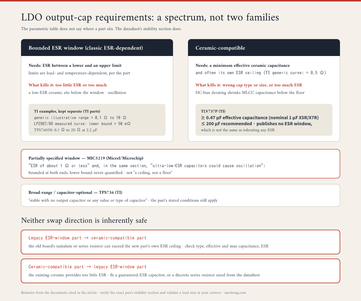
A pin-compatible swap is dangerous because output-capacitor requirements fall along a spectrum, and the parametric table gives no indication of where on that spectrum a given part belongs. Four shapes cover most datasheets.
| Requirement shape | What the datasheet specifies | What kills it |
|---|---|---|
| Bounded ESR window (classic ESR-dependent designs) | ESR between a lower and an upper limit, load-dependent (TI's generic example: ~0.1–10 Ω) | Too little ESR, as with a low-ESR ceramic, or too much |
| Ceramic-compatible | A minimum effective ceramic capacitance, often an upper ESR limit of its own (TI's generic ceramic-stable curve tops out around 0.5 Ω) and a maximum capacitance | The wrong capacitor type, an undersized capacitor after derating, or ESR above the part's own ceiling |
| Partially specified window | A stated ESR maximum together with a warning against ultra-low ESR, with no numeric lower limit | Reading the specification as a ceiling only, and fitting any ceramic |
| Broad-range / capacitor-optional | Stability over a wide range of capacitors, or with none at all (TI's TPS736: "stable with no output capacitor or any value or type of capacitor") | Little at the regulator itself, though network resonances and the part's stated conditions still apply |
Two named parts show how differently these requirements read on the page.
TI's TLV757P (datasheet SBVS322C, March 2024) is a modern ceramic-compatible device, and it expresses stability as a capacitance requirement instead of an ESR requirement. It asks for at least 0.47 µF of effective output capacitance, normally implemented as a nominal 1 µF X5R or X7R ceramic, with no more than 200 µF recommended, and it publishes no traditional ESR window. For the designer that is a real simplification. It is also a specific fact about a specific part, and generalizing it into "ceramic-stable devices tolerate any ESR" would be an error. TI's own generic ceramic-stable analysis shows that the internal compensation zero which removes the minimum ESR requirement also pushes the maximum stable ESR down, to roughly 0.5 Ω over much of the load range in its illustrative curve.
Micrel and Microchip's MIC5219 is the partially specified window in the flesh. The current document is Microchip DS20006021A, Revision A of May 2018, which converted the original Micrel datasheet of June 2009 and records minor text changes throughout. Its Output Capacitor section recommends a capacitor with "an ESR (equivalent series resistance) of about 1Ω or less and a resonant frequency above 1 MHz", then warns in the next sentence that "Ultra-low ESR capacitors could cause oscillation and/or under-damped transient response." Read the two sentences together and the acceptable ESR is effectively bounded at both ends, even though the datasheet never quantifies the lower bound. The specification should not be read as a ceiling alone, because the second sentence gestures at a floor the first one omits.
The same section states capacitance conditions worth reading carefully: 1 µF minimum output capacitance without the bypass capacitor, 2.2 µF minimum when a 470 pF bypass capacitor is fitted, and 22 µF minimum for outputs below 3 V. The reason for the second condition appears elsewhere in the document, where the reference bypass is discussed: "CBYP reduces the regulator phase margin; when using CBYP, output capacitors of 2.2 µF or greater are generally required to maintain stability." A capacitor fitted to quiet the reference therefore consumes stability margin, and the required output capacitance rises to compensate. Reading only the Output Capacitor section would have supplied the number without the reason for it.
Doing an LDO drop-in that stays stable
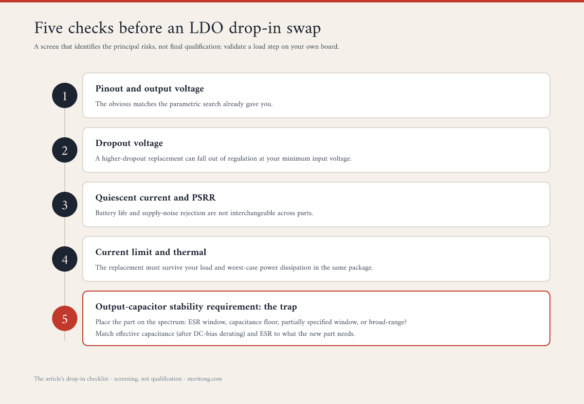
Match these five, and the swap has a chance.
Pinout and output voltage: the obvious ones, which the parametric search has already given you.
Dropout voltage: the input-to-output difference below which the LDO can no longer hold its regulation specification at a given load. For a MOSFET pass element it approximates the load current multiplied by the on-resistance, so it rises with load. Bipolar-pass LDOs follow a different mechanism, governed by saturation voltage and base drive, so compare the datasheet numbers at your load and your temperature instead of trusting the formula. A replacement with a higher dropout can fall out of regulation at your minimum input voltage even though the nominal output voltage matches.
Quiescent current and PSRR: where the design depends on battery life or supply-noise rejection, these figures are not interchangeable between parts that share a pinout.
Current limit and thermal behavior: the replacement has to survive your load and your worst-case power dissipation in the same package.
The output-capacitor stability requirement, which is the trap: read the replacement's stability and output-capacitor section, and place the part on the spectrum above. Then make the capacitor network on your board match what the new part requires. Check effective capacitance rather than the value printed on the component, because MLCCs lose a large fraction of their marked capacitance to DC bias, and TI's TLV757P guidance assumes 50% derating as a general rule. ESR itself moves with frequency and temperature. Count the whole rail as well, since distributed ceramic bypass capacitors downstream form their own pole; AN-1482 gives a worked example in which 1 µF of scattered bypass ceramics reduces an ESR-compensated loop's phase margin from 68° to about 9°. The old board's output network was chosen for the old regulator, and you should assume nothing about its suitability for the new one.
Getting step 5 right removes one major source of instability, and it does not finish the job. The substitution still has to be validated on the assembled board, with load-step testing at your real input voltage, load and temperature corners, watching for the ringing TI describes, and with attention to your input-source impedance. The checklist above deliberately says nothing about start-up behavior, enable thresholds, reverse current, noise or protection behavior, each of which has its own datasheet section.
Two directions, and neither is inherently safe
Both directions of substitution are common, and it is tempting to treat one of them as the harmless one.
Legacy ESR-window part → ceramic-compatible part: the temptation here is to leave the capacitor alone, on the grounds that the new part "likes ceramics." A board designed around an ESR-window LDO usually carries a tantalum or aluminum capacitor chosen deliberately for its ESR, and sometimes an explicit series resistor as well. That ESR can exceed the replacement's own ceiling, and TI's generic ceramic-stable limit of roughly 0.5 Ω gives a sense of the magnitude involved. Check the replacement's permitted capacitor type, minimum effective capacitance, maximum capacitance and ESR limits, then change the capacitor when the existing one falls outside them.
Ceramic-compatible part → legacy ESR-window part: here the existing low-ESR ceramic supplies almost none of the resistance the replacement's loop needs, and the rail can oscillate on the capacitor already fitted. Two fixes work. You can fit a capacitor whose guaranteed ESR stays inside the required range across frequency and temperature; ordinary MLCCs do not guarantee a minimum ESR, while tantalums with a specified ESR do. You can instead add a discrete resistor in series with the capacitor branch, placed between the output node and the capacitor rather than in series with the load, which synthesizes the ESR the loop requires, exactly as TI does to stabilize the TPS76050. Size that resistor from the part's stated stability range instead of increasing it until the ringing stops, and remember that the added resistance appears in the load-step response as an immediate ΔI × R voltage excursion.
The underlying point holds in both directions. The output capacitor network forms part of the LDO's compensation. Change the regulator, and you have re-opened the stability question, which gets answered in the datasheet's output-capacitor section and on your own hardware under a load step.
Reading the stability section fast
You do not need to be a control theorist to complete step 5. Open the replacement's datasheet and look first for a stable ESR range or a stability-region plot, which marks an ESR-dependent part you must match; note whether the limits are guaranteed or merely typical. Look next for a minimum ceramic capacitance with no ESR graph, which marks a ceramic-compatible part whose effective-capacitance floor you must meet.
If neither appears cleanly, check for the other shapes: a recommended capacitor chemistry, an ESR maximum accompanied by an ultra-low-ESR warning as in the MIC5219, load-dependent limits, requirements that change when a bypass or noise-reduction capacitor is fitted, or an explicit statement of stability with any capacitor or none. Read the bypass, noise and application sections as well as the stability section, since the MIC5219 states the reason for one of its own capacitance minimums outside the section that gives the number. Whatever you find, the absence of an ESR plot never licenses the assumption that any capacitor is safe. Then validate a load step on the bench.
FAQ
What is dropout voltage, exactly?
It is the minimum input-to-output headroom at which the LDO can still meet its regulation specification at a stated load. For an LDO with a MOSFET pass transistor, a useful first-order approximation in dropout is the load current multiplied by the pass element's on-resistance, so it rises with load; bipolar-pass LDOs have a different dropout mechanism. Below dropout, the loop can no longer hold the nominal output, and the output roughly follows the input minus the pass element's drop. A part with a higher dropout can therefore stop regulating at a low input voltage even where the nominal output voltage matches.
Why did my LDO start oscillating after I changed the output capacitor to ceramic?
One likely reason is that the LDO relies on the output capacitor's ESR for stability, and a ceramic supplies almost none of it, so the compensating zero moved out of reach and the loop lost phase margin. A ceramic swap also changes the effective capacitance and can add network poles, so ESR alone is not automatically the whole explanation. Three remedies are available: use a capacitor with the ESR the part requires, add a small series resistor in the capacitor branch, or move to an LDO specified for low-ESR ceramics.
What does "ceramic-stable" mean?
It means the LDO is designed and specified to remain stable with the stated low-ESR ceramic output capacitor over its specified operating conditions, and the internal technique for achieving that varies by device. The term does not license any capacitor at any ESR. You still have to meet the effective-capacitance floor, respect any maximum capacitance and allow for the fact that such parts can impose an upper ESR limit of their own. You also cannot conclude that an older part is ceramic-stable merely because a ceramic happens to be fitted on a working board.
Can I just add a resistor in series with the output cap?
For an ESR-dependent LDO oscillating on a ceramic, a discrete resistor in series with the capacitor branch does synthesize the ESR the loop needs, and TI demonstrates precisely this to stabilize a TPS76050. It is a valid fix with three caveats. Place it between the output node and the capacitor rather than in the load path, size it from the datasheet's stability range, and validate the load-step response across your operating corners, since the resistor also increases the immediate transient excursion.
Do parametric tools warn me about this?
Often they do not, at least not reliably. A parametric search matches voltage, current, dropout and package. The output-capacitor stability requirement is usually not a filterable field, and even where a tool flags a part as "ceramic compatible," the actual capacitance, ESR and operating-condition requirements still have to be checked in the datasheet's stability section, which is exactly the section a "same value" swap skips.
Can I tell from the parametric table whether an LDO is ceramic-stable?
Usually you cannot, at least not reliably. The requirement appears in the datasheet's output-capacitor and stability section, outside the filterable fields. Determine which shape the part specifies, whether an ESR window, a capacitance floor, a partially specified window or broad-range stability, and treat any LDO swap as unverified until you have read that section.
My replacement LDO is stable but runs hotter or noisier. Why?
Stability is only one of the specifications that fails to travel with the pinout. Quiescent current, PSRR, dropout and thermal performance can all differ between LDOs sharing a package and an output voltage, and PSRR in particular has to be compared at your frequency, load and headroom instead of as a single headline number. A part can be perfectly stable and still be a worse fit on power, noise or dropout, which is why the checklist above extends beyond the output capacitor.
Close
Substituting an LDO is one possible move when a regulator goes long-lead, doubles in price or reaches end of life, and it deserves a balanced verdict. A qualified alternate turns an allocation notice into a purchase order, often at a lower unit cost, and the qualification work you do once keeps its value for years. Against that, every substitution creates a new dependency, sometimes in a different jurisdiction with its own supply and policy exposure, and it costs engineering time before it saves anything. Whether it pays depends on your volume, your lifecycle, your regulatory obligations and how much analog validation capacity you have.
The discipline does not depend on any of that. The specification that decides whether the rail oscillates is absent from the comparison table, and no amount of parametric matching will surface it. TI put the evidence on record in two oscilloscope traces, where a single resistor separated a regulator from an oscillator.
A Second-Source Map cross-references your regulators on that basis. It matches the output-capacitor stability requirement instead of the pinout alone, and it names what still has to be validated on your own board, so that the drop-in stays a drop-in. If that would help, that is what I do.
This article explains a real, part-specific behavior using figures from the documents of the parts named: TI application notes AN-1482 (SNVA167A) and the TPS76050 report SLVA115A, the TI TLV757P (SBVS322C) and TPS736 datasheets, the Microchip MIC5219 datasheet (DS20006021A, Rev. A, May 2018), and ADI's Analog Dialogue tutorial on LDO concepts. It is general engineering guidance and not a specification for any particular LDO. Confirm the output-capacitor stability requirement in the datasheet of the exact part you use, and validate with load-step testing on your own board at your operating corners.
Get the next pattern by email
One dependency pattern from real hardware audits, occasionally. No schedule promised yet.
Working through this right now? Book a call → or write to me →